Download
1 / 8
80 likes | 176 Views
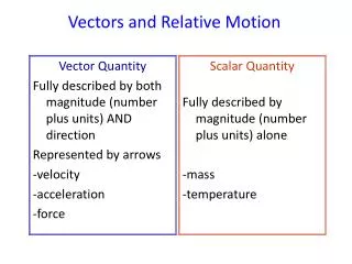
Some aspects of wavefront tilt and relative motion in the WaveTrain propagation code. Boris Venet 29 June 2006. Background.

E N D
Some aspects of wavefront tilt and relative motion in the WaveTrain propagation code Boris Venet 29 June 2006
Background • Several WaveTrain users (both internal and external to MZA) have been disturbed by a certain aspect of the wavefront tilt reported by WaveTrain when the receiver is moving relative to the source. • Analysis of the problem from the point of view of different reference frames seems (at first) to have some paradoxical features. • The issue is connected with concepts and methods of special relativity, but we can discuss and resolve the issue without the full relativity analysis machinery. (bv)
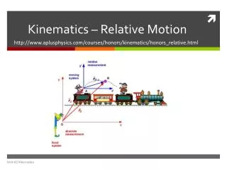
Propagation scenarioand Analysis 1 • In rest frame of source, let: • Source emit initially collimated beam with 0 tilt, or on-axis spherical wave • Receiver move transverse to propagation direction, with offsets and timing as shown Rec Rec Src Rec Receiver WT “Incoming” light Source • Provisional conclusion: analysis 1 implies that measured tilt (avg) of wavefront reported by sensor at t = L/c should be q’y = 0. (This was the logic assumed by the users mentioned on the Background slide). (bv)
Rec Rec Analysis 2 • Before inquiring what tilt WT reports, let’s do another thought experiment (analysis 2). Continue to visualize in rest frame of source • Explicitly consider time (f /c) required for wavefront to propagate from receiver pupil to image plane. • Image plane centroid, y’c , satisfies • The time at which result (2) is valid is slightly > (L /c), but if f <<L, this is for all practical purposes = (L /c).Note that angle is independent of f. • Typical (Vy /c) values: (10m/s) / 3E8m/s = 0.033 urad (1000m/s) / 3E8m/s = 3.3 urad • Provisional conclusion: “tilt” prediction from analysis 2 contradicts analysis 1 ??Suggests a non-unique connection between wavefront tilt and reported centroid ?? (bv)
0 0 SFS span WaveTrain answerfor the tilt at t = L/c • Images from the two WT sensors, at t = L/c (first data frames recorded by the runset timing setup).(Note that WT expLen =1E-12s, negligible) • WT’s tilt answer (from both sensors):q’y = - 3.3 urad = -(Vy /c) WT gives the “analysis 2” answer. • NOW, TWO QUESTIONS:(A) Is the WT answer right or wrong?(B) What logic did WT use? Note that WT got the “analysis 2” answer, but it definitely did not use that logic ... • SFS plane: dxy = 0.02 m • Cam foc plane: dxy/foclen = 0.195 urad Actual surface of constant phase (bv)
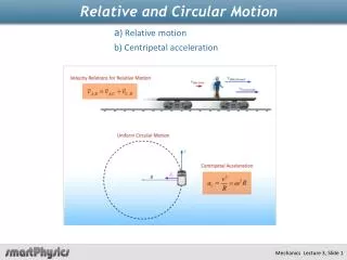
Analysis 3What WT actually does (and brilliantly, this time...) • In rest frame of receiver, we have the picture below • Analysis concept: at t=L/c, receiver senses light emitted by source at earlier (t=0) time • This light presumably has the tilt indicated at the receiver block diagram WT “Incoming” light Src Rec Src Wavefronts emitted at t=0 sensed at t=L/c Src • Provisional conclusion: analysis 3 implies that measured tilt (avg) of wavefront reported by sensor at t = L/c should be q’y = -(Vy /c). • Analysis 3 conclusion is same as analysis 2 conclusion, but disagrees with analysis 1. • Concept 3 is essentially the logic built into WaveTrain: WT’s transverse motion manipulations are based on visualizing the problem in the rest frame of the receiver. • Final question: is analysis 3 correct? After all, analysis 1 looks pretty convincing to some people. (bv)
Further analysis and final remarks • Analyses 1 and 2: we said those pictures were drawn from the point of view of the source, but really it’s a sort of God’s eye view of the situation • Formal analytical approach: write a formula that expresses the surface of constant phase in one reference system, and perform t-dependent coordinate transformation to obtain formula for surface in other system (“Galilean transformations”) • This approach yields same answer as analyses 2 and 3 (the WT answer) • Another picture frequently used that is equivalent to the formal coord transformation idea is to apply vector velocity addition to a point on the wavefront: c -Vy • Special Relativity works the problem from the point of view of formal coord transformations, but using the Fitzgerald-Lorentz transformations • Suggested homework: • WT plane wave case (slew complication) • Work out the formal Galilean coord coordinate transformation method (bv)