Download
1 / 59
610 likes | 789 Views
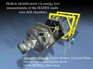
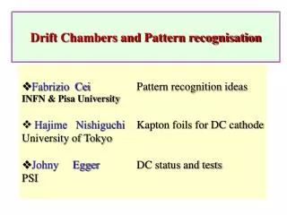
On the Multiwire Drift Chambers alignment of the HADES dilepton spectrometer. Héctor Alvarez Pol. 16 December 2002. INDEX. Part I The HADES Physics. Part II The HADES spectrometer. Part III Overview of the drift chambers alignment. Part IV Alignment using hardware methods.

E N D
On the Multiwire Drift Chambers alignment of the HADES dilepton spectrometer Héctor Alvarez Pol 16 December 2002
INDEX Part I The HADES Physics Part II The HADES spectrometer Part III Overview of the drift chambers alignment Part IV Alignment using hardware methods Part V Alignment using software algorithms Conclusions
THE HADES PHYSICS PROGRAM Heavy ion collisions at SIS energies
THE HADES PHYSICS PROGRAM Heavy ion collisions at SIS energies
THE HADES PHYSICS PROGRAM Heavy ion collisions at SIS energies
THE HADES PHYSICS PROGRAM Heavy ion collisions at SIS energies
THE HADES PHYSICS PROGRAM Want to know! Observables Behavior of the High Density Phase In-medium change of ρ, ω, φ masses • Partial restoration of the chiral symmetry • Equation of State (EOS) • Astrophysics: neutron stars and inner stars structure In-medium dilepton decays are not affected by strong interactions!
THE HADES PHYSICS PROGRAM Dilepton invariant mass spectra In-medium vector meson decay External vector meson decay
THE HADES PHYSICS PROGRAM These series of experiments, exploiting the full range of primary and secondary beams available at GSI, are expected to make important contributions to our understanding of Quantum Chromodynamics in the non-perturbative regime and, in particular, will provide information on the origin of hadron masses. From The HADES Physics Program, J. Friese and V. Metag
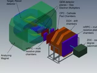
THE HADES SPECTROMETER HADES installation at GSI
THE HADES SPECTROMETER HADES features Capability to deal withhigh count rates and large particle multiplicities to accumulate enoughsignificant events in a finite time Low mass materials are chosen in all detectors and supportstructures to minimize the multiple scattering Excellent mass resolution ( Dm/m » 1 % (σ) at ω mass) should allow the individual identification of the vector mesons A selective trigger scheme able to accept only those events withlepton pairs, mainly those of high mass Rejection of hadronic and electromagnetic background whichcould obscure the dilepton signal Large dilepton acceptance (~40% for lepton pairs), required because of the tiny dileptonbranchingratio, of the order of 10-5. Allows the comprehensive studies of the behavior of vector mesons in the nuclear medium Flat acceptance in mass and in transverse momentum Large dilepton acceptance Rejection of hadronic and em. background Excellent mass resolution Flat acceptance in mass and in mT High count rates Large particle multiplicities Low mass materials A selective trigger scheme
THE HADES SPECTROMETER Large dilepton acceptance Rejection of hadronic and em. background Excellent mass resolution Flat acceptance in mass and in mT High count rates Large particle multiplicities Low mass materials A selective trigger scheme
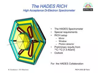
THE HADES SPECTROMETER RICH: Ring Imaging Cherenkov Detector RICH
THE HADES SPECTROMETER RICH: Ring Imaging Cherenkov Detector RICH
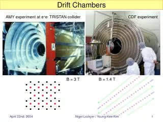
THE HADES SPECTROMETER MDCs: Multiwire Drift Chambers MDCs MDCs RICH
THE HADES SPECTROMETER MDCs: Multiwire Drift Chambers MDCs MDCs RICH
THE HADES SPECTROMETER MDCs: Multiwire Drift Chambers MDCs • MDC features: • High position resolution MDCs RICH • Operation on Isobutane-Helium mixture to reduce the multiple scattering • Two track detection ability
THE HADES SPECTROMETER ILSE: Superconducting Toroidal Magnet MDCs MDCs RICH ILSE
THE HADES SPECTROMETER TOF TOF: Time-of-Flight Detectors MDCs MDCs RICH ILSE TOF
THE HADES SPECTROMETER Pre-Shower: Electromagnetic/Hadronic Shower Detector With Lead Converters TOF MDCs Pre-Shower MDCs RICH ILSE Pre-Shower TOF
THE HADES SPECTROMETER TOF TOFino: lower angle Time-of-Flight MDCs Pre-Shower MDCs RICH TOFino ILSE Pre-Shower TOF
OVERVIEW OF THE DRIFT CHAMBERS ALIGNMENT Steps towards theHADES alignment system • Revision of the momentum reconstruction methods in the spectrometer • Simulation of the misalignment effects on the reconstructed momentum • Analysis of the architectural design and evaluation of the technical resources • Definition of a specific alignment scheme
OVERVIEW OF THE DRIFT CHAMBERS ALIGNMENT The tracking system
OVERVIEW OF THE DRIFT CHAMBERS ALIGNMENT Opposite directions for e - and e+ Dependent on the misaligned MDC Approx. linear behavior
OVERVIEW OF THE DRIFT CHAMBERS ALIGNMENT Simulation results Momenta between 400 and 600 MeV/c Electrons Positrons MDC Δp/p (%/100μm) Δp (MeV/c/100μm) Δp/p (%/100μm) Δp (MeV/c/100μm) I-0.21-1.1 -0.32 -2.2 II 0.130.7 0.19 1.3 III0.341.70.473.3 IV -0.27 -1.4-0.37-2.6 • Maximum misalignment of the MDCs (according to Physics criteria): • Δy ~ 50 μm along the particle magnetic kick direction • Also allows the determination of maximum deviation in the tilt angles
OVERVIEW OF THE DRIFT CHAMBERS ALIGNMENT After the analysis of the architectural design and the evaluation of the allowable displacements of the support structures and other constraints, the proposed and implemented alignment scheme consist of: • Software algorithms, based on the analysis and minimization of residuals or other functions of the hits in the drift chambers, using data samples with the magnetic field off. • Hardware sensors (RASNIK), monitoring the relative displacements of theexternal MDCs with respect to the inner ones, during the data taking period.
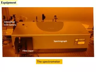
ALIGNMENT USING HARDWARE METHODS RASNIK: Red Alignment System from NIKHEF
ALIGNMENT USING HARDWARE METHODS Two emitters on the external MDCs frame Camera and lenses fixed to the internal MDCs frame IR light path
ALIGNMENT USING HARDWARE METHODS Parameters of the innovative setup 1. Angle between the sensor plane and the image plane 2. Aperture of the lens
ALIGNMENT USING HARDWARE METHODS Resolution analysis procedure Experimental setup Second order polynomial fit Conclusions: • The resolution improves for the smallest apertures • The resolution is practically independent of the incident angle • For α≥30°, the analysis module starts to fail Selected setup Lens aperture 15 mm Angle with sensor plane 25°
ALIGNMENT USING HARDWARE METHODS Epoxy Carbon Fiber: KT = - 0.5x10⁻⁶ K-1 Binocular design
ALIGNMENT USING HARDWARE METHODS Focus adjustment Optical axis adjustments Binocular
ALIGNMENT USING HARDWARE METHODS IR LEDs Matrix Mask Mount Mask and LEDs supports
ALIGNMENT USING HARDWARE METHODS Calibration Stable calibration terms in different parts of the mask Stable calibration terms for different masks
ALIGNMENT USING HARDWARE METHODS EPICS Operator Screen RAHAD online monitor • Distributed monitor screens • Archiver facilities • Internal raw data check • ROOT graphics facilities
ALIGNMENT USING HARDWARE METHODS Complete data sample Reduced data sample Complete data sample σ( XMDC ) = 3.86 μm σ( YMDC ) = 4.64 μm σ( Z MDC ) = 6.88 μm Reduced data sample σ( XMDC ) = 1.23 μm σ( YMDC ) = 1.55 μm σ( Z MDC ) = 2.5 μm ZMDC Resolution estimation XMDC YMDC
ALIGNMENT USING HARDWARE METHODS Experimental results Correlation with the temperature of the MDC frames Correlation with the magnetic field
ALIGNMENT USING SOFTWARE METHODS MDC to Lab: MDC to MDC: where and for instance Coordinate transformations
ALIGNMENT USING SOFTWARE METHODS Variables: Probability density function: Equiprobability volume (hyperellipsoids on α4): Hit compatibility and sample selection
ALIGNMENT USING SOFTWARE METHODS b a Three MDCs alignment algorithm should be zero for each track. Then, minimize with: where, for instance: A B C
ALIGNMENT USING SOFTWARE METHODS Simulation results If one parameter is fixed to the correct value Convergence inside the allowable error Below 50 μm The problem reduces to find out a set of histograms which univocally defines the correct value of the fixed parameter.
ALIGNMENT USING SOFTWARE METHODS b b b a a a c c c How to fix the angular parameter 2.06x10⁻³ 8.6x10⁻⁵ Abscissa for y=0 -6.6x10⁻⁵ -1.93x10⁻³
ALIGNMENT USING SOFTWARE METHODS Differences in mrad November 2001 alignment: three MDCs algorithm • The uncertainties in the calibration procedures and hit fitting tasks lead to hits with incompatible slopes on the MDCs. • As a consequence, the uncertainty intervals for the alignment results in Nov01 are slightly larger than expected (~100 μm for MDCs I-II, ~300 μm for MDCs II-III).
ALIGNMENT USING SOFTWARE METHODS Two MDCs alignment Minimization of the residuals: Analytical minimization with respect to the components of the translation vector: The solution is the relative translation vector V=(V0,V1,V2)
ALIGNMENT USING SOFTWARE METHODS Two MDCs alignment Geometrical determination of the relative rotations, for instance, in-plane rotations: θ