Download
1 / 26
260 likes | 326 Views
Project: IEEE P802.15 Working Group for Wireless Personal Area Networks (WPANs) Submission Title: [ TG4a Proposal for Low Rate DS-UWB (DS-UWB-LR)] Date Submitted: [ January 2004 ] Source: [Matt Welborn (1), Michael McLaughlin (2), & Shariar Emami (1)]

E N D
Project: IEEE P802.15 Working Group for Wireless Personal Area Networks (WPANs) Submission Title: [TG4a Proposal for Low Rate DS-UWB (DS-UWB-LR)] Date Submitted: [January 2004] Source: [Matt Welborn (1), Michael McLaughlin (2), & Shariar Emami (1)] Company [(1) Freescale Semiconductor, Inc, (2) decaWave, Ltd.] Address [8133 Leesburg Pike, Vienna VA 22182] Voice:[703-269-3000], FAX: [], E-Mail:[matt.welborn @ freescale.com, or michael@decawave.com] Re: [Response to Call for Proposals] Abstract: [This document describes a proposal for the TG4a baseline draft standard.] Purpose: [Proposal Presentation for the IEEE802.15.4a standard.] Notice: This document has been prepared to assist the IEEE P802.15. It is offered as a basis for discussion and is not binding on the contributing individual(s) or organization(s). The material in this document is subject to change in form and content after further study. The contributor(s) reserve(s) the right to add, amend or withdraw material contained herein. Release: The contributor acknowledges and accepts that this contribution becomes the property of IEEE and may be made publicly available by P802.15. Welborn, Freescale
UWB for Low Rate Communications • UWB has great potential for low power communications • Low fading margin can provide same range for lower transmit power • Large (ultra-wide) bandwidth can provide fine time resolution provides potential for accurate ranging – primary differentiation from existing 15.4 capabilities • Drawbacks due to regulations • Limited transmit power – how much is enough? • Operation at long ranges is highly dependent on NLOS path loss characteristics Welborn, Freescale
Proposal for TG4a Alternate PHY Layer Welborn, Freescale
Overview of DS-UWB-LR TG4a Proposal • Based on higher rate DS-UWB proposal under consideration in TG3a, but modified for low power and lower complexity • Variable-length code spreading with BPSK modulation of data • Chip rates are 1/3 the rates used in DS-UWB (so about 450 MHz) • Bandwidth is only ~500 MHz (instead of ~1500 M) • Lower complexity FEC convolutional code (constraint length k=4) • Data rates of 30 kbps to 10 Mbps • Use spreading codes of length 24 to 6144 • AWGN range of 15 to 75 meters (assuming n=3.5 PL at > 10m) • Support for precise ranging • Very straight forward solutions using RTT measurements with corrections for non-direct-path propagation effects • Flexible pulse shaping • Allows many pulse generation, antenna and receiver architectures • Supports requirements for coexistence & regulatory constraints • Will enable interoperation between higher rate DS-UWB devices and low rate, low complexity TG4a devices • Support wider range of asymmetric applications • Enables active coexistence and coordination Welborn, Freescale
Benefits of Low Rate DS-UWB • Bandwidth & operating frequency • Transmit power, ranging, complexity & performance • Pulse rate • Effects on efficiency & implementation • Data Rate • Interoperability & Coexistence Welborn, Freescale
Operating Frequency • If multiple bands used: • Multiple operating channels with different center frequencies to provide FDM operation for different networks • Three piconet bands at 3536, 4056, and 4576 MHz • Different performance due to 20 Log10(Fc) term in path loss • Also uses CDM for sharing of each band by different piconets • Could also use pure CDM in a single wider band • Could even mix wider band devices (1500 MHz) and narrower band devices (500 MHz) • Cost of generating the reference frequency depends on the specific frequency • DS-UWB is based on low cost, high quality 26 MHz crystals (widely used in cell phones) • Better frequency accuracy can relax other system constraints • Acquisition at longer range requires longer integration and therefore more accurate reference frequency • High accuracy clock can allow longer “sleep” time & better power management • Precise ranging using TOA methods requires high precision time measurements over relatively long intervals (RTT) to determine small differences in signal propagation times • Simplified and improved with good reference clock Welborn, Freescale
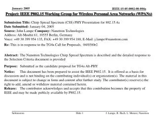
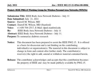
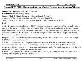
Signal Operating Bands for Low Rate UWB Relative PSD (dB) Possible Lower Rate Signaling Bands (500 MHz bandwidth) High rate DS-UWB Low Band with RRC Pulse Shape 0 -3 FCC Mask -20 3536 4056 4576 Frequency (MHz) 3100 5100 • Ultra-wideband ~500+ MHz bands for each piconet • Code-division and Frequency-division multiplexing • Multiple piconets in each band using different codes • Operation in close proximity, interference avoidance or coexistence • Three piconet bands at 3536, 4056, and 4576 MHz Welborn, Freescale
Low Rate DS-UWB Pulse Rate • “Impulse radio” (IR) originally meant low pulse rate (10’s of M pulse/sec) using “time hopping” for multiple access and pulse position modulation (PPM) • More generally, IR is just pulse-based spread spectrum with data modulation • Many choices for modulation (BPSK, PPM, OOK, etc.) • One or more pulses per data symbol • Low rate DS-UWB uses a chip rate that is designed to meet minimum 500 MHz bandwidth for simple BSK modulation • Center frequency is always a multiple of 26 MHz • Chip rate is equal to center frequency divided by 9 (e.g. 4052 / 9 = 450.66MHz) • Spreading codes are based on 24-chip code • Longer spreading codes are derived from the basic code by further sreading with PN sequence (e.g. length 192 code is a length 24 code spread by a length 8 PN code) • Pulse rate does not fundamentally affect transmit power, signal bandwidth or system performance • Pulse rate does affect energy per pulse and therefore peak power (and voltage) Welborn, Freescale
Higher Pulse Rate = Lower Peak Power Higher peak power & voltage for same average power • Lower pulse rate requires higher “energy per pulse” and therefore higher peak power (and voltage) for same transmit power • Process technology can limit available peak voltage that can be achieved without an external power amplifier ___ • If pulse rate is 100x slower, then peak voltage is 100 = 10x higher Welborn, Freescale
Something Special about Impulse Radio • For impulse radio, basic idea was to send a fixed pulse shape at a regular (or controlled) interval • For conventional carrier systems, the “pulse shape” at RF is not fixed due to lack of fixed relationship between carrier phase and symbol clock phase • Result: if properly designed we can have combine the benefits of conventional carrier-based systems and impulse systems • Fixed phase relationship between carrier & symbol • DS-UWB is based on integer relationship between center frequency (carrier) and chip or symbol rate • Makes frequency synthesis and implementation easier Welborn, Freescale
No Advantage to Non-Coherent Given that synchronization to chipping clock must be done regardless, and Since RF is easily synchronized to the chipping clock, There is no reason not to build coherent systems Chipping Clock Must Be Synchronized Regardless of Coherent/Incoherent Approach - Ring - up a filter to create an RF UWB pulse + Simple injection lock or PLL Ring No jitter issues because of high BW Oscillator (only 3X multiply) A very small ring oscillator at 4.1 GHz + Injection lock or PLL - an LC oscillator Welborn, Freescale
Data Rate Considerations • Lowest PHY data rate does not necessarily mean lowest energy consumption • In fact, a fast radio can potentially be more energy efficient than a slow radio. Example: • Compare a 1 Mbps radio at 100 mW versus 10 kbps radio at 10 mW • 32 kB @ 10 kbps = 0.256 mW*seconds • 32 kB @ 1 Mbps = 0.0256 mW*seconds – 1/10 of the energy per bit! • Assumptions • Both radios achieve minimum range requirement for application • Minimum acquisition time is a function of SNR (range) not data rate • Requires fast wake-up and shut down of radio with aggressive power management • Relative energy usage depends on packet size • Fast radio advantage is higher for longer packets • Notice transmit power is a small fraction of the total power (<1%) • The largest power use is turning on the radio and processing signal Welborn, Freescale
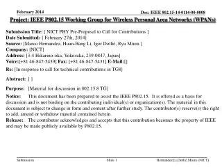
Data Rate Considerations Lower radio power, but longer transmission time for data payload Power Preamble Time Higher peak power but shorter transmission time for same payload Power Preamble Time • Total energy use from battery is the “area” under the power vs. time curves shown above • Relative efficiency depends on power & duration (payload size) Welborn, Freescale
Low Rate DS-UWB Data Rates • LR-DS-UWB data rates are designed to support relatively high rate operation at relatively small duty cycle Welborn, Freescale
Link Budget Welborn, Freescale
Link Budget Notes • Assumptions • Chipping rate = 450.66 MHz • Includes 1.9 dB Tx power reduction for spectral ripple in certification testing • Assumes 3.8e-5 BER to achieve 1% PER with 32 octet data packet Welborn, Freescale
Interoperability & Coexistence • All of the specific co-existing systems in the Slection Requirements are out-of-band to LR-DS-UWB • Robustness against in-band interference is provided by the UWB bandwidth of the LR-DS-UWB system (large processing gain) • Many types of other UWB systems and waveforms will share the UWB bands • Interoperability between TG4a & higher rate systems could enable improved coexistence • Interoperation with higher rate systems could increase the utility of the TG4a standard • Interoperability of low cost sensor/RFID devices with nearby UWB CE devices • Interoperability with DS-UWB could be quite simple if correct parameters are chose for TG4a • Common reference frequency, codes & operating bands Welborn, Freescale
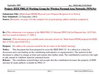
Dual 15.4 and DS-UWB (15.3a Proposal) is Easy and Could Provide Interoperability/Co-existence Receiver LNA ò To ADC S / H Ternary Code 3 n RF Cycles { + 1 , 0 , - 1 } Encoded Ant per Chip TxData Filter Code Gen LPF Code Clock Chip Clock d Sense r D x 3 n Q Ck This is as simple as anything else Symbol Rate L code Chip Rate Clock Idealized n = 1 for 1 . 5 GHz BW ( 15 . 3 a ) n 1 0 - 1 - 1 1 - 1 1 1 n = 3 for 500 MHz BW ( 15 . 4 a ) Filtered (LPF + RF) 1 . 352 GHz ( 104 * 13 MHz ) Inverted , Non - Inverted and Zero - Amplitude Wavelets Agile Clock Locks to Chip Rate Welborn, Freescale
Ranging using the DS-UWB Approach • TG4a has done an extensive review of potential location techniques – thank you! • Some result in hyperbolic lines of position (LOP) • Some result in circular LOPs (since they are determined directly from node-to-node ranges) • Simple node-to-node ranging can also be useful when used without the benefit of fixed reference nodes • Brief review of node-to-node ranging Welborn, Freescale
Basic Approach for Ranging Packet Exchange Timeline Delay before data is transmitted Total elapsed time Response Initiating packet Node A Node B Initiating packet Response Delay in receiver before ACK is transmitted T due to multipath excess delay T due to direct path propagation Welborn, Freescale
Required Measurements Node A Computes Range Node A Initiates Ranging Operation TX_Initialize (Node A) Sync_Ref_Point (Node A) Node A Excess Delay Estimate Total elapsed time Node A Channel Scan Response packet Initiating packet Node B later sends data to A Sync_Ref_Point (Node B) TX_Initialize (Node B) Inter-packet time Node B Initiating packet Response packet Channel Scan Node B Excess Delay Estimate Welborn, Freescale
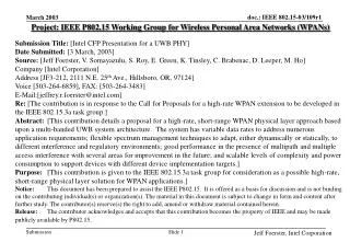
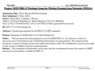
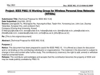
Example NLOS Range Calculations Nine Different NLOS Channel Impulse Responses, Ranges 16-25 Feet -3 x 10 3 2 Amplitude 1 0 -1 -2 -3 0 0.2 0.4 0.6 0.8 1 1.2 1.4 1.6 1.8 2 -7 Time (seconds) x 10 Leading Edges of Reponses, Showing Direct Path Component Detection -3 x 10 1.5 16.7 ft-1-1 17.9 ft-2-1 24.1 ft-4-1 1 18.7 ft-3-1 Amplitude 0.5 0 -0.5 20.5 ft-5-1 23.5 ft-8-1 22.4 ft-7-1 -1 21.4 ft-6-1 21.2 ft-9-1 -1.5 200 220 240 260 280 300 320 Range (in inches) Welborn, Freescale
Measured Multipath Resolution with an Operating Radio Optimal lock path for radio 14 dB lower power Multipath component amplitude (dB) Earliest arriving path 10 ns earlier Time in nanoseconds (time reversed) Welborn, Freescale
Technical Feasibility • The Low rate DS-UWB solution for TG3a has a high level of manufacturability • Based on existing DS-UWB technology • Can be implemented in low-cost CMOS technology • Time to Market • Time to market should be quite reasonable. • Regulatory Impact • DS-UWB technology is know to be compliant with FCC UWB rules • Other regulatory administrations are using FCC rules as a basis for initial discussions • Many mechanisms exist to ensure compliance for other regions that adopt other regulations Welborn, Freescale
System Performance • System and SOP simulations are underway – results TBD Welborn, Freescale
Collaboration – What’s Important Welborn, Freescale