Download

1 / 10
100 likes | 118 Views
Discover the meticulous work and operational plans of the Antiproton Target Station Group in improving antiproton targets for efficient production. Gain insights into target designs, cooling effectiveness, and performance evaluations.

E N D
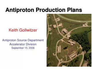
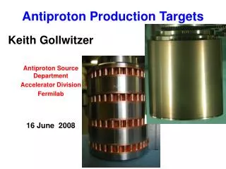
Antiproton Production Targets Keith Gollwitzer Antiproton Source Department Accelerator Division Fermilab 16 June 2008
Disclaimer • I am not well versed in targets • The Antiproton Target Station Group of the Mechanical Support Department of the Accelerator Division have been working for years on the improvements of the target, lens, collimator and pulsed magnet • I can put you in contact with the engineers involved with the target station
Style A Target Target stack consists of target disks (nickel alloy) and copper heat sinks Air is directed through the center of cylinder from the top and then through the copper baffle sections Beam goes through a chord of the target disk Target stack is rotated ~17o after each proton pulse Entire target stack is moved vertically to fresh target material Style has been in use for several years
Style A Target This target stack was installed Dec 27 and removed May 22 Precision beam control needed to not target copper Heat sink and target material separation can be seen; lose cooling effectiveness Believed missing material caused by oxidation which leads to weakened material that is then subject to beam Nominal spot size ~200μm; smaller beam size causes “sputtering” which can coat the lens with unwanted heat sources
Style B Target No stacking of disks; target cylinder means nearly twice as much target material Center of target cylinder still has air flow with heat sink Heat sink consisted of deformed copper balls brazed together and to inner copper tube. Beryllium cover to remove chance for oxidation as well as keeping sputtered material contained.
Operational Plan • Run normal beam until see degradation • Run ~1 week with no beam sweeping • Run a few days with reduced spot size (with beam sweeping) • Check visually for any problems • Ran 1 week and saw change in air flow • Compromised heat exchanger • Ran additional 10 days before degradation • Ran two days with no beam sweeping • Saw opportunity to do last step; ran less than one day with smaller spot size
Operational Plan • Run normal beam until see degradation • Run ~1 week with no beam sweeping • Run a few days with reduced spot size (with beam sweeping) • Check visually for any problems • Ran 3 days and saw change in air flow • Compromised heat exchanger • Ran additional 2 weeks before degradation • Ran two days with no beam sweeping • Saw opportunity to do last step; ran less than one day with smaller spot size • Rotation problem
Style B Target Ran 17 days of normal beam conditions. After 3 days heat exchanger disappeared Can see heat band on beryllium cover Probably developed crack after losing cooling Note that we ran without moving target stack for >2X longer than Style A Target. Also note discoloration at top probably due to excessive heat
Style B Target Ran less than a day with smaller spot size and beam sweeping Lack of target cooling and targeting near bottom of disk caused the beryllium cover to move and interfere with rotation Can see shift in cover pieces Can see where targeted for two days without sweeping Can see evidence for sputtering at last position Don’t know if large cover separation was before/after rotation problems
Status and Plans • Believe failure of heat exchanger led to further problems • Believe better performance with Style B Target has been achieved • Have all material and parts for Style A Target; will assemble • Have all material for Style B Target; design more robust heat exchanger followed by assembly of complete target • Will complete both in next few months; current Style A target should last 4-5 months