Download
1 / 19
190 likes | 300 Views
A New Equivalent Circuit Extraction Method For Quasi-static Regions. Benjamin D. Braaten Dr. Robert M. Nelson Yuxin Feng. North Dakota State University. Topics. Introduction Computing the equivalent circuit Validation Conclusion. North Dakota State University. Introduction.

E N D
A New Equivalent Circuit Extraction Method For Quasi-static Regions Benjamin D. Braaten Dr. Robert M. Nelson Yuxin Feng North Dakota State University
Topics • Introduction • Computing the equivalent circuit • Validation • Conclusion North Dakota State University
Introduction • Recently, Electric Field Integral Equations (EFIE) were developed for evaluating problems with [1] • electrically large regions (full-wave regions) • electrically small regions (quasi-static regions) • geometrically complex quasi-static regions • thin-wire full-wave regions • But, problems with a large number of quasi-static regions (>4) have resulted in a long computation time [1]. [1] B.D. Braaten, R.M. Nelson and M.A. Mohammed, “Electric field integral equations for electromagnetic scattering problems with electrically small and electrically large regions,” IEEE Transactions on Antennas and Propagation, Vol. 56, No. 1, January 2008, pp. 142-150 North Dakota State University
Introduction • This has lead to the development of modeling these quasi-static regions as equivalent circuits [1],[2]. • This will allow the quasi-static regions to be represented as equivalent circuits in fast efficient full-wave solvers such as Mininec [3]. [1] B.D. Braaten, R.M. Nelson and M.A. Mohammed, “Electric field integral Equations for electromagnetic scattering problems with electrically small and electrically large regions,” IEEE Transactions on Antennas and Propagation, Vol. 56, No. 1, January 2008, pp. 142-150 [2] R.G. Olsen, G.L. Hower and P.D. Mannikko, “A hybrid method for combining Quasi-static and full-wave techniques for electromagnetic scattering problems,”IEEE Transactions on Antennas and Propagation, Vol. 36, No. 8, pp. 1180-1184,August 1988. [3] J.W. Rockway and J.C. Logan, “The New MININEC (Version 3): A Mini-numerical Electromagnetics code,” U.S. Department of Commerce National Technical Information Service, Springfield, VA September 1986, pp. 1-21. North Dakota State University
Introduction • In this work we introduce a method for determining the equivalent circuit of a quasi-static region based on work by Mayhan et.al. [4]. • This method can then be used to determine the equivalent circuit of a quasi-static region that may not have a convenient analytical method for evaluating the equivalent circuit. [4] J.T. Mayhan, A.R. Dion and A.J. Simmons, “A technique for measuring antenna drive port Impedance using backscatter data,” IEEE Transactions on Antennas and Propagation, Vol. 42, No. 4, April 1994, pp. 526-533. North Dakota State University
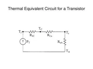
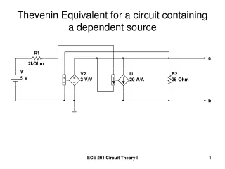
Computing the equivalent circuit First, consider the following equation: scattered field from known load scattered field from short circuit (1) known load admittance antenna admittance scattered field from open circuit North Dakota State University
Computing the equivalent circuit Rearranging (1) and using impedance values we get: scattered field from unknown load scattered field from short circuit (2) known antenna input impedance impedance attached to the port of the antenna scattered field from open circuit North Dakota State University
Computing the equivalent circuit Step 1: Redefine the quasi-static region at the port of a test dipole with a known input impedance and calculate .
Computing the equivalent circuit Step 2: Remove the quasi-static region at the port of the test dipole with a known input impedance and short the terminals to calculate . North Dakota State University
Computing the equivalent circuit • Step 3: Remove the short at the port of the test dipole and open the terminals to calculate . • Then use (2) to calculate the equivalent circuit of the quasi-static region. • All computations can be performed in QUICNEC [1]. North Dakota State University
Validation • The first problem chosen to validate the method presented here was a capacitively dominant quasi-static region. North Dakota State University
Validation • Using the scattered field method an equivalent circuit of Ro=0 and Co=.32pF was calculated. • This problem also results in an analytical equivalent circuit approximation of .28pF (epsilon A/d). North Dakota State University
Validation The following two problems were then defined in QUICNEC and Mininec for validation. North Dakota State University
Validation This resulted in the following input reactance. North Dakota State University
Validation • The second problem used to validate the method was a two insulator wire problem. • This problem was chosen because is may not be very easy to calculate an equivalent circuit analytically. North Dakota State University
Validation • Using the method described here an equivalent circuit of Ro=1251 Ohms and Co=.00692pF was calculated. • This resulted in the following induced current at 1340 KHz. • The equivalent circuit was defined in Mininec. North Dakota State University
Computation time • First problem: QUICNEC 57 seconds and Mininec <1 second. • Second problem: QUICNEC 6 minutes and Mininec < 1 second. North Dakota State University
Conclusion • A method for determining the equivalent circuit based on various scattered fields has been presented. • Two problems have been chosen to validate the method • a capacitively dominant quasi-static region • a quasi-static insulator • It has been shown that this method can be used to accurately model quasi-static regions in Mininec. • Finally, a significant savings in computation time is observed. North Dakota State University
Questions Thank you for listening North Dakota State University