Download
1 / 37
410 likes | 659 Views
GSM RF Planning and Engineering Aspects. Introduction Single Band Optimization Philosophy Network Optimization Process Optimization Phases Lucent BSS Optimization Parameters Cell Selection/ Cell Reselection Power Control Procedures Handover Procedures Drive Testing and Analysis

E N D
GSM RF Planning and Engineering Aspects
Introduction Single Band Optimization Philosophy Network Optimization Process Optimization Phases Lucent BSS Optimization Parameters Cell Selection/ Cell Reselection Power Control Procedures Handover Procedures Drive Testing and Analysis Drive Test Equipment AGENDA
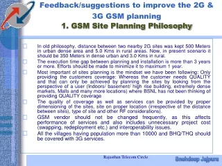
What is Optimization ? - Activity of achieving and maintaining the required quality as designed Why Optimization ? - Deviations between plan and reality Introduction
What is Optimization ? Design Optimization Planning Implementation
Why Optimization ? • Inaccuracy of radio planning • - Statistical variations in the path loss characteristics • - Finite terrain database resolution • Implementation • - Antenna radiation pattern and effective radiated power • - Antenna pattern distortion • Environment • - Seasonal environmental changes, e.g trees, leaves • - Environmental changes such as new highways, new buildings
Coverage - Good signal level across the whole cell, coverage holes within a cells service area must be minimized. Interference - A reasonable level of interference must be contained at cells service area in order to provide a quality air-interface. Handover Behavior - The quality of the air-interface in a cell with respect to handover behavior is good, no unnecessary handovers, Rxquality at acceptable level, BTS & MS use minimum transmit power. Traffic Distribution - The quality of the air-interface in a cell with respect to traffic distribution is good, maximum amount of traffic can be handed. Single Band Optimization Philosophy
Optimization Phases • Site Audit • Proper Parameters use • Verify Neighbors list • Reviewing Frequency Plan Initial Optimization c • Verify existing coverage, site design objectives • Analysis & Identification of Problem areas/cells • from PMS & drive test statistics, • customer complaints • Prioritization of problems • Identify Solution and Implement • Retest the problem areas • Consistency Check of the OMC database • Fine-tuning of parameters Primary Optimization c • On going process, weekly optimization • Database maintenance and consistency audits Maintenance Optimization
CELL (RE) SELECTION POWER CONTROL HANDOVER CONTROL Lucent BSS parameters related to Optimization
Areas of improvement : Minimization of interference Handover behavior improvement Traffic distribution Lucent BSS parameters related to Optimization
Cell (Re)Selection 2 cell (re)selection criteria: C1 & C2 ? ?
C1 Criteria Used for cell selection and re-selection C2 Criteria Used in a hierarchical cell structure for re-selection only Cell (Re)Selection
C1 = (A-Max(B,0)) where: A = Received Level Average - RXLEV_ACCESS_MIN B = MS_TXPWR_MAX_CCH - max.output power of the MS Criteria met if C1> 0. MS will camp on to the cell with the highest C1 value. Cell (Re)Selection
Cell Reselect Hysteresis Location Update 1 Location Update 2 LAC 1 LAC 2
Cell Reselect Hysteresis Reselect Hysteresis LAC1 Reselect Hysteresis LAC2 LAC 1 LAC 2
Power Control Signal Level Range (in dBm) 0 1 2 3 .. .. .. .. .. 62 63 Rxlevel < -110 -110 < Rxlevel < -109 -109 < Rxlevel < -108 -108 < Rxlevel < -107 .. .. .. .. .. -49 < Rxlevel < -48 Rxlevel > -48 SIGNAL LEVELS
Power Control Signal Quality Range (in BER) BER < 0.2 0.2 < BER < 0.4 0.4 < BER < 0.8 0.8 < BER < 1.6 1.6 < BER < 3.2 3.2 < BER < 6.4 6.4 < BER < 12.8 BER > 12.8 0 1 2 3 4 5 6 7 SIGNAL QUALITY LEVELS
TYPES OF HANDOVERS Mandatory HO RXQUAL RXLEVEL DISTANCE Power Budget HO Duration of stay counter (Hierarchical Cell) Handover Control • Preprocessing to support the following handover types: Internal Intra-Cell Handover (BSC-controlled) Internal Inter-Cell Handover (BSC-controlled) External Inter-Cell Handover (MSC-controlled) • Inter Cell Handover may occur from: SDCCH to SDCCH SDCCH to TCH (directed retry) TCH to TCH
Handover Control Rxlevel (received by MS) SERVER ------------------------------------------------------------------------------- HO_MARGIN ------------------------------------------------------------------------------- -------------------- NEIGHBOR Handover Time Power Budget Handover Margin
Handover Procedures • HO Process • BTS measures the UL and DL measurements every 480 ms. • RXLEV-XL • RXQUAL-XL • RXLEV-NCELL(1-6) • DIST (timing advance) • BTS reports measurements to BSC. • BSC calculates the averaged parameters using a sliding window: • AV-RXLEV-HO • AV-RXQUAL-XL-HO • AV-RXLEV-SCELL • AV-RXLEV-NCELL(I) • AV-DIST • BSC decides the HO execution by comparing with threshold values. • Handover Algorithm Basic Steps • HO Measurement Averaging (Preprocessing) • HO Threshold Comparisons • HO Target Cell Identification • HO Decision (BSC internal or MSC) • HO Execution (BSC internal or MSC)
Performance Determinants Coverage Interference Handover Behaviour Traffic Distribution Optimization Solutions Enable/Disable GSM features BSS parameters Neighbour cell lists Antenna tilt, height & azimuth Frequency changes BSS Optimization Parameters Discontinuous Transmission • Decreases interference level • Saves battery power (uplink) Frequency Hopping • Decrease interference • Suppress Rayleigh Fading Power Control • Saves battery power • Decrease interference level
Drive Testing and Analysis • Trouble Ticket • - Is a document by which various problems reported by customers are passed along through the organization • - Must reply upon experience and knowledge to determine which option to overcome the problem • - Different scenarios can be followed to solve the problem, such as drive testing, parameters changes, antenna adjustment, etc….. • - To verify if the problem is not related to MS itself
Drive Testing and Analysis • Air Interface Information • - RXLEVEL • - RXQUALITY • - BCCH, BSIC of the serving cell • - BCCH, BSIC and RXLEVEL of the 6 best neighbours • - TIMING ADVANCE • - GSM BEST SERVER
Drive Testing and Analysis • Drive Testing • - Propagation Measurements • - Mobile Network Performance Monitoring • Quality Assessment • Optimization
Drive Testing and Analysis • Drive Tests for Optimization • - Initial network coverage verification and benchmarking • - Verification before and after changes • - Locating and measuring interference • - Locating areas where traffic problems exist • - Locate coverage holes • - Preventive maintenance • - Simultaneous measurements of the other networks
Drive Testing and Analysis • Drive Test Data Collection • - CELL ID including BSIC, LAC, and time slot • - RXLEVEL for the serving and the neighbour cells • - RXQUALITY for the serving cell • - BCCH, BSIC for the serving and the neighbour cells • - TIMING ADVANCE • - TRANSMIT POWER • - GPS POSITION DATA • - TIME STAMPS
Drive Testing and Analysis • Drive Test Route Planning • - Primary route(street level) • Includes all major roads,highways and wide thoroughfares • - Secondary route(street level) • Includes all streets, subdivisions and compounds when accessable • - Miscellaneous routes (in-building and special locations) • Includes golf courses, beach resorts, shopping mails, department stores, convention centers, hotels and resorts
Drive Testing and Analysis • Performance Problems that often encountered: • - Cell Dragging • - Dropped Calls • - Ping-Ponging • - System Busy • - Handover boundary
Drive Testing and Analysis • Cell Dragging - Calls may drag a cell beyond the desired handover boundary. This might result dropped calls or bad Rxquality. • Suggestions: • Create an appropriate neighbour cell list • Change HO parameters such as thresholds, margin, cell baring, etc • Check serving cell’s cell identifier in the neighbour cell’s neighbour list • Check neighbour cell’s BCCH, BSIC, LAC, Cell ID, etc
Drive Testing and Analysis • Dropped Calls - Caused by either RF environments or incorrect system parameters • Suggestions: • Check if an appropriate neighbour cell list is defined • Check HO parameters • Existing or new coverage holes • Interference, Co-channels, Adjacent channels or External interference • Serving cells might go down, coverage smaller as before • Abnormalities such as call setup failure
Drive Testing and Analysis • Ping Ponging - Serving keep changing and as a result of bad audio quality • Suggestions: • Check if an appropriate neighbour cell list is defined • Check HO parameters • Interference, Co-channels, Adjacent channels or External interference • Lack of dominant server • Poor coverage • Not optimal antenna configuration
Drive Testing and Analysis • System Busy - System busy on several call attempts and site appears consistently on the traffic report • Suggestions: • Short Term • Reduce the traffic on the congested cell/site. However, the proposed changes MUST NOT create any unacceptable problems such as coverage holes, dropped calls, etc • Shot term solutions are re-design the antenna configuration, • Add additional RTs, Change BTS configuration • Long Term • Build a new cell site to off-load traffic
Drive Testing and Analysis • Handover Boundary - Handovers do not occur at the desired HO boundary, the result is an imbalance in traffic distribution across the system • Suggestions: • Check if an appropriate neighbour cell list is defined • Check HO parameters • Inappropriate antenna configurations of the serving and neighbour cells • Interference, Co-channels, Adjacent channels or External interference • No TCH available (neighbour cells congestion)
Drive Test Equipment • Typical example of drive test equipment components: • Test Mobile phone • Scanning receiver • Transceiver system • Antennas • GPS • Visual display unit • Microphone • Loudspeaker box • Laptop computer
ERICSSON TEMS 900/1800 Test 2 Network simultaneously Full Layer 2 & 3 decoding Control of Layer 3 msg Forced selection of idle and dedicated mode Filtering msg streams Rxqual in idle mode Sending SMS SIM card information Drive Test Equipment COMARCO WIRELESS • Test 4 networks simultaneously • GSM 900/1800, ETACS, AMPS • Partial Layer 2 & 3 decoding • Fast scanning receiver, GSM RF Spectrum • Ability to display adjacent channel interference screen • Noise measurements SAFECO WALKABOUT • In-building coverage
AGILENT TECHNOLOGIES(HP) Test 4 networks simultaneously Fast scanning receiver, UL & DL Frequency Hopping Table Spectrum Analysis Channel Power CW Measurement Interference Measurement GSM Broadcast Channel Analysis Drive Test Equipment QVOICE98 • Test 4 networks simultaneously • Evaluate measurement both way • Good Presentation • Capable on measuring MOS, Speech Quality, Rxquality, Rxlevel