Download
1 / 48
500 likes | 602 Views
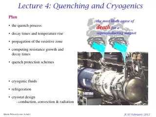
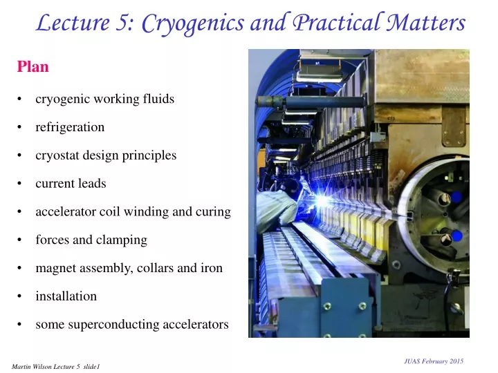
Plan cryogenic working fluids refrigeration cryostat design principles current leads accelerator coil winding and curing forces and clamping magnet assembly, collars and iron installation some superconducting accelerators. Lecture 5: Cryogenics and Practical Matters.

E N D
Plan cryogenic working fluids refrigeration cryostat design principles current leads accelerator coil winding and curing forces and clamping magnet assembly, collars and iron installation some superconducting accelerators Lecture 5: Cryogenics and Practical Matters JUAS February 2015
Cryogenics: the working fluids the gap * enthalpy change of gas from boiling point to room temperature represents the amount of 'cold' left in the gas after boiling - sometimes called ‘sensible heat’ JUAS February 2015
the most basic refrigerator uses compressor power to extract heat from low temperature and reject a larger quantity of heat at room temperature Carnot says the Coefficient of Performance CoP = cooling power / input power Refrigeration wc compressor . m expansion engine we . Q liquid 15 10 5 CoP qh = 320K at 4.2K CoP = 1.3% JUAS February 2015
Collins helium liquefier wc compressor . m . Q we heat exchangers we liquid gas from compressor heat exchanger - cooled by upstreaming gas heat exchanger - cooled by upstreaming gas expansion turbine - cooled by doing work repeat expansion valve - cooled by Joule Thompson effect gas liquid from Helium Cryogenics SW Van Sciver pub Plenum 1986 JUAS February 2015
helium has the lowest boiling point of all gases and is therefore used for cooling superconducting magnets below thelamda pointa second liquid phase forms, known as Helium 2 or superfluid it has zero viscosityand very high thermal conductivity Some numbers for helium boiling point at 1 atmos 4.22K lamda point at 0.0497 atmos 2.17K density of liquid at 4.22K 0.125 gm/cc density of gas at 4.22K 0.0169gm/cc density of gas at NTP 1.66x10⁻⁴gm/cc latent heat of vaporization 20.8J/gm enthalpy change 4.2K293K 1506J/gm ratio Denthalpy/latent heat 72 Properties of Helium JUAS February 2015
Subcooled Helium II pump out gas at 0.016atm 1 atm gas 4.2K 1 atm liquid 1.8K nozzle He 1 He 2 valve • HeII is an excellent coolant because of its high thermal conductivity and specific heat • NbTi works much better at the lower temperature • but for practical engineering, it is inconvenient operate at pressures below atmospheric • the 'lamda plate' allows us to produce HeII in a system operating at atmospheric pressure • used in LHC and commercial NMR magnets JUAS February 2015
Accelerator magnet cryostat essentials current supply leads high vacuum radiation shield liquid helium beam tube magnet feeds to next magnet mechanical supports JUAS February 2015
1) Gas conduction at low pressures (<10Pa or 10-4 torr), that is when the mean free path ~ 1m > distance between hot and cold surfaces Cryogenic heat leaks where hg depends on the accommodation coefficient; typical values for helium not usually a significant problem, check that pressure is low enough and use a sorb 2) Solid conduction look up tables of conductivity integrals a more convenient form is 3) Radiation transfer between two surfaces heat flux Stefan Boltzmann constant s = 5.67x10⁻⁸ Wm-2K-4 4) Current Leadsoptimization problem; trade off Ohmic heating against conducted heat - lecture 5 5) Other sourcesac losses, resistive joints, particle heating etc JUAS February 2015
radiated power goes as q4 can reduce it by subdividing the gap between hot and cold surface using alternating layers of shiny metal foil or aluminized Mylar and insulating mesh. structure must be open for vacuum pumping. Superinsulation hot surface shiny metal insulating mesh cold surface Some typical values of effective emissivity er for superinsulation * Jehier SA BP 29-49120 Chemille France JUAS February 2015
Current Leads current in room temp gas out copper liquid helium Optimization • want to have low heat inleak, ie low ohmic heating and low heat conduction from room temperature. This requires lowrand k - but Wiedemann Franz says • so all metals are the same and the only variable we can optimize is the shape • Gas cooling helps (recap helium properties above) • Denthalpy gas / latent heat of boiling = 73.4 - lots more cold in the boil off gas • so use the enthalpy of the cold gas which is boiled off to cool the lead • we make the lead as a heat exchanger JUAS February 2015
Current lead theory helium gas • where: • f = efficiency of heat transfer to helium gas • = helium mass flow • Cp= specific heat of gas • solution to this equation in 'Superconducting Magnets p 257. • there is an optimum shape (length/area) which gives the minimum heat leak • - 'Watts per Amp per lead' • heat leak is a strong function of the efficiency of heat transfer f to the cold gas room temp equation of heat conduction JUAS February 2015
Heat leak of an optimised lead • with optimum shape and 100% efficient heat transfer the heat leak is 1.04 mW/Amp per lead • with optimum shape and no heat transfer the heat leak is 47 mW/Amp • Note the optimum shape varies with the heat transfer efficiency JUAS February 2015
Optimum shape of lead • the optimum shape depends on temperature and material properties, particularly thermal conductivity. • for a lead between 300K and 4.2K the optimum shape is - for a lead of annealed high purity copper • L = length, A = area of cross section, A = area • for a lead of impure phosphorous deoxised copper (preferred) JUAS February 2015
Impure materials make more stable leads • for an optimized lead, the maximum temperature is room temperature (at the top of the lead) • when the lead is not optimized, the temperature of an intermediate region rises above room temperature • the optimum for pure metals is more sensitive than for impure metals if current lead burns out magnet open circuit large voltages disaster JUAS February 2015
Health monitoring • all leads between the same temperatures and with the same cooling efficiency drop the same voltage at optimum • for a lead between 300K and 4.2K with with 100% cooling efficiency, the voltage drop at optimum is 75mV • measure the volts across your lead to see if it is optimised • if a lead burns out, the resulting high voltage and arcing (magnet inductance) can be disastrous • monitor your lead and trip the power supply if it goes too high JUAS February 2015
room temp copper coolant gas heat leak heat leak HTS HTS High temperature superconductor Current leads • at temperatures below 50 -70K can use HTS • material has very low thermal conductivity • no Ohmic heat generation • but from room temperature to 50 – 70 K must have copper leads • the 50 – 70 K junction must be cooled or its temperature will drift up and quench the HTS • For the HTS section beware of • overheating if quenches • fringe field from magnet JUAS February 2015
He gas out heat exchanger 20K He gas in HTS section HTS current leads for LHC • HTS materials have a low thermal conductivity • make section of lead below ~ 70K from HTS material • heat leak down the upper lead is similar, but it is taken at a higher temperature less refrigeration power • LHC uses HTS leads for all main ring magnets • savings on capital cost of the refrigerator > cost of the leads • reduced running cost is a continuing benefit • 13kA lead for LHC 600A lead for LHC pictures from A Ballarino CERN JUAS February 2015
Winding the LHC dipoles photo courtesy of Babcock Noell JUAS February 2015
End turns Constant Perimeter end spacers • if the cable is pulled tight • it sits in the right place JUAS February 2015
Spacers and insulation polyimide insulation Kapton copper wedges • copper wedges between blocks of winding • beware of voltages at quench • care needed with insulation, between turns and ground plane • example: FAIR dipole quench voltage = 340V over 148 turns JUAS February 2015
Compacting and curing • After winding, the half coil, (still very 'floppy') is placed in an accurately machined tool • Tool put into a curing press, compacted to the exact dimensions and heated to 'cure' the polyimide adhesive on the Kapton insulation. • After curing, the half coil is quite rigid and easy to handle JUAS February 2015
Curing press photo CERN JUAS February 2015
Finished coils photo CERN after curing, the coil package is rigid and relatively easy to handle photo CERN JUAS February 2015
Coils for correction magnets On a smaller scale, but in great number and variety, many different types of superconducting correction coils are needed at a large accelerator photo CERN JUAS February 2015
Electromagnetic forces in dipoles B F I Fy Fy LHC dipole Fx ~1.6106 N/m = 160 tonne/m Fx F = B^ I Fx • forces in a dipole are horizontally outwards and vertically towards the median plane • recap lecture 2 slide 12, for a thin winding total outward force per quadrant total vertical force per quadrant • the outward force must be supported by an external structure • Fx and Fycause compressive stress in the conductor and insulation • apart from the ends, there is no tension in the conductor for thick winding take ~ mean radius JUAS February 2015
Collars • Question: how to make a force support structure that • fits tightly round the coil • presses it into an accurate shape • has low ac losses - laminated • can be mass produced cheaply • Answer: make collars by precision stamping of stainless steel or aluminium alloy plate a few mm thick • - inherited from conventional magnet laminations press collars over coil from above and below push steel rods through holes to lock in position invert alternate pairs so that they interlock JUAS February 2015
Collars LHC dipole collars support the twin aperture coils in a single unit photo CERN photo CERN 12 million produced for LHC photo CERN JUAS February 2015
LHC dipole collars sub-units of several alternating pairs are riveted together stainless rods lock the sub-units together photo CERN JUAS February 2015
Pre-loading the coil measure the pressure here capacitance data from Siegal et al CERN data during manufacture and operation data from Modena et al JUAS February 2015
Collars and end plate (LHC dipole) photo CERN • sliding at the outer boundary friction heating • use kapton layers photo CERN JUAS February 2015
Adding the iron stainless shell photo CERN • pushed into place using the collaring press • BUTpure iron becomes brittle at low temperature • tensile forces are therefore taken by a stainless steel shell which is welded around the iron, while still in the press • stainless shell also serves as the helium vessel iron laminations • iron • laminations assembled on • the collared coil JUAS February 2015
Compressing and welding the outer shell JUAS February 2015
Dipole inside its stainless shell photo CERN JUAS February 2015
Cryogenic supports 4K 78K 300K 'feet' used to support cold mass inside cryostat (LHC dipole) the Heim column • long path length in short distance • mechanical stiffness of tubes • by choosing different material contractions can achieve zero thermal movement photo CERN JUAS February 2015
Complete magnet in cryostat photo CERN photo CERN photo Babcock Noell JUAS February 2015
Make the interconnections - electrical photo CERN JUAS February 2015
Make interconnections - cryogenic photo CERN JUAS February 2015
Connect to the cryogenic feed and current leads photo CERN JUAS February 2015
Fermilab Tevatron the world's first superconducting accelerator photo courtesy of Fermilab • Rutherford cable • porous winding • force supporting collars • warm iron photo Fermilab JUAS February 2015
DESY Hera PSU PSU photo courtesy of DESY • Rutherford cable • porous winding • force supporting collars • cold iron JUAS February 2015
RHIC:Relativistic Heavy Ion Collider photos BNL JUAS February 2015
CERN LHC photo courtesy of CERN • Rutherford cable • porous winding and He 2 • force supporting collars and cold iron • two coils in one structure JUAS February 2015
Facility for Antiproton and ion research FAIR SIS 100 SIS 300 SIS 18 UNILAC Radioactive Ion Production Target Existing facility:provides ion-beam source and injector for FAIR HESR Super FRS Anti-Proton Production Target FAIR will accelerate a wide range of ions, with different masses and charges. So, instead of beam energy, we talk about the bending power of the rings as 100T.m and 300T.m (field x bend radius) CR 100 m FLAIR RESR NESR JUAS February 2015
FAIR: two rings in one tunnel SIS 300: ‚Stretcher‘/ high energy ring Modified UNK dipole6T at 1T/s SIS 100: Booster & compressor ring Nuclotron-type dipole magnet: B=2T, dB/dt=4T/s 2x120 superconducting dipole magnets 132+162 SC quadrupole magnets JUAS February 2015
Problem of the sagitta in SIS300 L s q R two straight magnets must be short because of sagitta B = 6T must use double layer coil curved magnet has no sagitta, can be long, save space of end turns B = 4.5T can use single layer coil Discorap curved dipole INFN Frascati / Ansaldo JUAS February 2015
Heliossynchrotron X-ray source superconducting dipole unloading at IBM microchip production facility NY, USA photo Oxford Instruments photo Oxford superconducting dipoles high field tight bending radius compact size transportability JUAS February 2015
Helios dipole photo Oxford • bent around180 • rectangular block coil section • totally clear gap on outer mid plane for emerging X-rays (12 kW) JUAS February 2015
Cryogenics & Practical Matters: concluding remarks what comes next up to you • liquid helium for low temperature and liquid nitrogen for higher – but a gap for HTS • making cold takes a lot of energy – the colder you go the more it takes so must minimize heat leaks to all cryogenic systems - conduction – convection - radiation • current leads should be gas cooled and the optimum shape for minimum heat leak, shape depends on the material used impure material is less likely to burn out use HTS to reduce heat leak at the bottom end • making accelerator magnets is now a well established industrial process wind compact collar iron cryostat install interconnect • in recent years all the largest accelerators (and some small ones) have been superconducting customer helpline martnwil@gmail.com JUAS February 2015