Download
1 / 20
290 likes | 1.58k Views
Disc Resonator Gyroscope (DRG). Jared Satrom Chris Fruth. Goal of the Project. To conduct research and analysis of a novel MEMS gyroscope design 1) Understand the motivation for the new patent from Boeing and Honeywell and others; why higher performance?

E N D
Disc Resonator Gyroscope(DRG) Jared Satrom Chris Fruth
Goal of the Project • To conduct research and analysis of a novel MEMS gyroscope design 1) Understand the motivation for the new patent from Boeing and Honeywell and others; why higher performance? 2) Identify new features in the novel design(s) and how higher performances are achieved 3) Compare to existing gyroscope designs 4) Analyze Q (quality) factor improvements
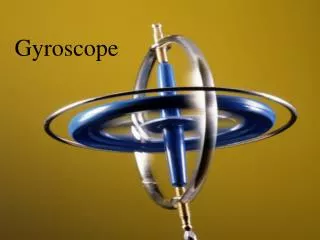
Disc Resonating Gyro Basics • Gyroscope is driven to resonate in-plane • Electrodes sense deflection in outer ring sockets • Electrodes actuate in inner ring sockets • Circuits process the signal and feedback into the system
Coriolis Effect • Coriolis acceleration (a) occurs if a resonating disc is pterturbed • Depends on velocities on the disc higher frequencies allow Coriolis acceleration to dominate centrifugal acceleration • Coriolis acceleration is what the electrodes sense through change in capacitance
How Does the DRG Work? • DC Source creates an electrostatic force that moves the disc • Proper control of these electrodes can put the system into resonance • Similarly, the sensing electrodes use gap changes to gauge system changes
One Ring or Many? • One major advantage of this system is its large area • Compared to a single ring gyro, has much more control over actuation and sensing • Single rings require flexible support beams as well
Why Cut the Circles? • With full concentric circles, the structure tends to be rigid • By using arcs instead, the structure becomes more flexible, allowing for better accuracy and performance
Ideal Gyro • High-Q • Large S/N ratio • Low-cost • Small (1 cm3) • Reliable • Requiring low power
Q-Factor • Quality factor Q is the measure of energy dissipation
Issue: Energy Dissipation Mechanisms • Thermoelasticity: Mechanical energy is exchanged for thermal energy that is diffused • Scattering Loss: “Elastic wave” of resonation is scattered due to material defects • Anchor Loss: Elastic waves travel down the support column of the disc and dissipate • Fluid Damping: Less significant, only a problem for low frequency applications
Benefits of this Design • Has large sensing area compared to other gyros • Easy to package • Multiple sensing and driving electrodes can make it easier to operate and read
Advantages Over Other Designs • MEMS gyroscopes desirable because they are lightweight and cheaper to produce • Isolation from vehicle platform is desirable to limit transmission of external disturbances • A design incorporating: • high sensitivity (as in hemispherical resonators) • simple/inexpensive thin planar Si microfabrication (as in a thin ring gyroscope)
Motivation for Higher Performance • Scalability of previous gyroscope designs was poor: • mechanical features were hard to perfect at smaller scales • Sensor noise scales less than size • Therefore, smaller yet more precise and accurate gyros are desired • Adequate areas for driving and sensing while remaining compact
The Future of MEMS Gyros • Smaller • Cheaper • Not limited to Silicon • Ti More durable • Nano and Picosatellites • Submarine & Aircraft satellite launches • Image-stabilizing cellphones?