Download

1 / 130
1.39k likes | 1.71k Views
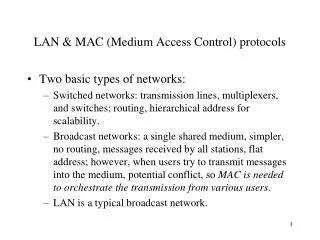
Chapter 6 Medium Access Control Protocols and Local Area Networks. Part I: Medium Access Control Part II: Local Area Networks. Broadcast Networks All information sent to all users No routing Shared media Radio Cellular telephony Wireless LANs Copper & Optical Ethernet LANs

E N D
Chapter 6 Medium Access Control Protocols and Local Area Networks Part I: Medium Access Control Part II: Local Area Networks
Broadcast Networks All information sent to all users No routing Shared media Radio Cellular telephony Wireless LANs Copper & Optical Ethernet LANs Cable Modem Access Medium Access Control To coordinate access to shared medium Data link layer since direct transfer of frames Local Area Networks High-speed, low-cost communications between co-located computers Typically based on broadcast networks Simple & cheap Limited number of users Chapter Overview
Chapter 6 Medium Access Control Protocols and Local Area Networks Part I: Medium Access Control Multiple Access Communications Random Access Scheduling Channelization Delay Performance
Chapter 6 Medium Access Control Protocols and Local Area Networks Part II: Local Area Networks Overview of LANs Ethernet Token Ring and FDDI 802.11 Wireless LAN LAN Bridges
Chapter 6Medium Access Control Protocols and Local Area Networks Multiple Access Communications
3 2 4 1 Shared multiple access medium 5 M Multiple Access Communications • Shared media basis for broadcast networks • Inexpensive: radio over air; copper or coaxial cable • M users communicate by broadcasting into medium • Key issue: How to share the medium?
Approaches to Media Sharing Medium sharing techniques Static channelization Dynamic medium access control • Partition medium • Dedicated allocation to users • Satellite transmission • Cellular Telephone Scheduling Random access • Polling: take turns • Request for slot in transmission schedule • Token ring • Wireless LANs • Loose coordination • Send, wait, retry if necessary • Aloha • Ethernet
Channelization: Satellite Satellite Channel downlink fout uplink fin
Channelization: Cellular uplink f1 ; downlink f2 uplink f3 ; downlink f4
Inbound line Outbound line Host computer Stations Scheduling: Polling Data from 1 Data from 2 Poll 1 Data to M Poll 2 M 2 1 3
Scheduling: Token-Passing Ring networks token Data to M token Station that holds token transmits into ring
Crash!! Random Access Multitapped Bus Transmit when ready Transmissions can occur; need retransmission strategy
Wireless LAN AdHoc: station-to-station Infrastructure: stations to base station Random access & polling
Selecting a Medium Access Control • Applications • What type of traffic? • Voice streams? Steady traffic, low delay/jitter • Data? Short messages? Web page downloads? • Enterprise or Consumer market? Reliability, cost • Scale • How much traffic can be carried? • How many users can be supported? • Current Examples: • Design MAC to provide wireless DSL-equivalent access to rural communities • Design MAC to provide Wireless-LAN-equivalent access to mobile users (user in car travelling at 130 km/hr)
Delay-Bandwidth Product • Delay-bandwidth product key parameter • Coordination in sharing medium involves using bandwidth (explicitly or implicitly) • Difficulty of coordination commensurate with delay-bandwidth product • Simple two-station example • Station with frame to send listens to medium and transmits if medium found idle • Station monitors medium to detect collision • If collision occurs, station that begin transmitting earlier retransmits (propagation time is known)
B does not transmit before t = tprop & A captures channel Case 1 A B B transmits before t = tprop and detectscollision soon thereafter Case 2 A B A detects collision at t = 2 tprop A B Two-Station MAC Example Two stations are trying to share a common medium Distance d meters tprop = d / seconds A transmits at t = 0 A B
Efficiency of Two-Station Example • Each frame transmission requires 2tprop of quiet time • Station B needs to be quiet tprop before and after time when Station A transmits • R transmission bit rate • L bits/frame Normalized Delay-Bandwidth Product Delay-Bandwidth Product Average frame length
Typical MAC Efficiencies Two-Station Example: • If a<<1, then efficiency close to 100% • As a approaches 1, the efficiency becomes low CSMA-CD (Ethernet) protocol: Token-ring network a΄= latency of the ring (bits)/average frame length
Typical Delay-Bandwidth Products • Max size Ethernet frame: 1500 bytes = 12000 bits • Long and/or fat pipes give large a (Delay-Bandwidth = PropDelay * bits/second, where PropDelay = meters / 3*10^8mps
MAC protocol features • Delay-bandwidth product • Efficiency • Transfer delay • Fairness • Reliability • Capability to carry different types of traffic • Quality of service • Cost
MAC Delay Performance • Frame transfer delay • From first bit of frame arrives at source MAC • To last bit of frame delivered at destination MAC • Throughput • Actual transfer rate through the shared medium • Measured in frames/sec or bits/sec • Parameters R bits/sec & L bits/frame X=L/R seconds/frame l frames/second average arrival rate Load r = l X, rate at which “work” arrives Maximum throughput (@100% efficiency): R/L fr/sec
E[T]/X Transfer delay 1 r rmax 1 Load Normalized Delay versus Load E[T] = average frame transfer delay • At low arrival rate, only frame transmission time • At high arrival rates, increasingly longer waits to access channel • Max efficiency typically less than 100% X = average frame transmission time
a > a E[T]/X a a Transfer Delay 1 r rmax rmax 1 Load Dependence on Rtprop/L
Chapter 6Medium Access Control Protocols and Local Area Networks Random Access
X X Prior interval frame transmission ALOHA Model • Definitions and assumptions • X frame transmission time (assume constant) • S: throughput (average # successful frame transmissions per X seconds) • G: load (average # transmission attempts per X sec.) • Psuccess : probability a frame transmission is successful • Any transmission that begins during vulnerable period leads to collision • Success if no arrivals during 2X seconds
Abramson’s Assumption • What is probability of no arrivals in vulnerable period? • Abramson assumption: Effect of backoff algorithm is that frame arrivals are equally likely to occur at any time interval • G is avg. # arrivals per X seconds • Divide X into n intervals of duration D=X/n • p = probability of arrival in D interval, then G = n p since there are n intervals in X seconds
Throughput of ALOHA • Collisions are means for coordinating access • Max throughput is rmax=1/2e (18.4%) • Bimodal behavior: Small G, S≈G Large G, S↓0 • Collisions can snowball and drop throughput to zero e-2 = 0.184
Slotted ALOHA • Time is slotted in X seconds slots • Stations synchronized to frame times • Stations transmit frames in first slot after frame arrival • Backoff intervals in multiples of slots Backoff period B t (k+1)X t0+X+2tprop kX t0+X+2tprop+ B Time-out Vulnerableperiod Only frames that arrive during prior X seconds collide
0.368 Ge-G S 0.184 Ge-2G G Throughput of Slotted ALOHA
Application of Slotted Aloha cycle • Reservation protocol allows a large number of stations with infrequent traffic to reserve slots to transmit their frames in future cycles • Each cycle has mini-slots allocated for making reservations • Stations use slotted Aloha during mini-slots to request slots . . . . . . Reservation mini-slots X-second slot
Station A begins transmission at t = 0 A Station A captures channel at t = tprop A Carrier Sensing Multiple Access (CSMA) • A station senses the channel before it starts transmission • If busy, either wait or schedule backoff (different options) • If idle, start transmission • Vulnerable period is reduced to tprop(due to channel capture effect) • When collisions occur they involve entire frame transmission times • If tprop >X (or if a>1), no gain compared to ALOHA or slotted ALOHA
CSMA Options • Transmitter behavior when busy channel is sensed • 1-persistent CSMA (most greedy) • Start transmission as soon as the channel becomes idle • Low delay and low efficiency • Non-persistent CSMA (least greedy) • Wait a backoffperiod (without sensing), then sense carrier again • High delay and high efficiency • p-persistent CSMA (adjustable greedy) • Wait till channel becomes idle, transmit with prob. p; or wait one mini-slot time & re-sense with probability 1-p • Delay and efficiency can be balanced Sensing
S 0.53 a = 0.01 0.45 0.16 a =0.1 G a = 1 1-Persistent CSMA Throughput • Better than Aloha & slotted Aloha for small a • Worse than Aloha for a > 1
Non-Persistent CSMA Throughput a = 0.01 S • Higher maximum throughput than 1-persistent for small a • Worse than Aloha for a > 1 0.81 0.51 a = 0.1 0.14 G a = 1
CSMA with Collision Detection (CSMA/CD) • Monitor for collisions & abort transmission • Stations with frames to send, first do carrier sensing • After beginning transmissions, stations continue listening to the medium to detect collisions • If collisions detected, all stations involved stop transmission, reschedule random backoff times, and try again at scheduled times • In CSMA collisions result in wastage of X seconds spent transmitting an entire frame • CSMA-CD reduces wastage to time to detect collision and abort transmission
A begins to transmit at t = 0 A B B begins to transmit at t = tprop- ; B detects collision at t = tprop B A A detects collision at t= 2 tprop- A B CSMA/CD reaction time It takes 2 tpropto find out if channel has been captured
(a) Busy Contention Busy Idle Contention Busy Time CSMA-CD Model • Assumptions • Collisions can be detected and resolved in 2tprop • Time slotted in 2tprop slots during contention periods • Assume n busy stations, and each may transmit with probability p in each contention time slot • Once the contention period is over (a station successfully occupies the channel), it takes X seconds for a frame to be transmitted • It takes tprop before the next contention period starts.
Contention Resolution • How long does it take to resolve contention? • Contention is resolved (“success’) if exactly 1 station transmits in a slot: • By taking derivative of Psuccess we find max occurs at p=1/n • On average, 1/Pmax = e = 2.718 time slots to resolve contention
Busy Contention Busy Contention Busy Contention Busy CSMA/CD Throughput Time • At maximum throughput, systems alternates between contention periods and frame transmission times • where: R bits/sec, L bits/frame, X=L/R seconds/frame a = tprop/X nmeters/sec. speed of light in medium d meters is diameter of system 2e+1 = 6.44
CSMA-CD Application: Ethernet • First Ethernet LAN standard used CSMA-CD • 1-persistent Carrier Sensing • R = 10 Mbps • tprop = 51.2 microseconds • 512 bits = 64 byte slot • accommodates 2.5 km + 4 repeaters • Truncated Binary Exponential Backoff • After nth collision, select backoff from {0, 1,…, 2k – 1}, where k=min(n, 10)
For small a: CSMA-CD has best throughput For larger a: Aloha & slotted Aloha better throughput CSMA/CD 1-P CSMA Non-P CSMA max Slotted ALOHA ALOHA a Throughput for Random Access MACs
Carrier Sensing and Priority Transmission • Certain applications require faster response than others, e.g. ACK messages • Impose different interframe times • High priority traffic sense channel for time t1 • Low priority traffic sense channel for time t2>t1 • High priority traffic, if present, seizes channel first • This priority mechanism is used in IEEE 802.11 wireless LAN
Chapter 6Medium Access Control Protocols and Local Area Networks Part II: Local Area Networks Overview of LANs Ethernet Token Ring and FDDI 802.11 Wireless LAN LAN Bridges
Chapter 6Medium Access Control Protocols and Local Area Networks Overview of LANs
What is a LAN? Local area means: • Private ownership • freedom from regulatory constraints of WANs • Short distance (~1km) between computers • low cost • very high-speed, relatively error-free communication • complex error control unnecessary • Machines are constantly moved • Keeping track of location of computers a chore • Simply give each machine a unique address • Broadcast all messages to all machines in the LAN • Need a medium access control protocol
RAM RAM Typical LAN Structure • Transmission Medium • Network Interface Card (NIC) • Unique MAC “physical” address Ethernet Processor ROM
Medium Access Control Sublayer • In IEEE 802.1, Data Link Layer divided into: • Medium Access Control Sublayer • Coordinate access to medium • Connectionless frame transfer service • Machines identified by MAC/physical address • Broadcast frames with MAC addresses • Logical Link Control Sublayer • Between Network layer & MAC sublayer
OSI IEEE 802 Network layer Network layer 802.2 Logical link control LLC Data link layer 802.11 Wireless LAN Other LANs 802.3 CSMA-CD 802.5 Token Ring MAC Physical layer Various physical layers Physical layer MAC Sub-layer
C A Reliable frame service A Unreliable Datagram Service C LLC LLC LLC MAC MAC MAC MAC MAC MAC PHY PHY PHY PHY PHY PHY Logical Link Control Layer • IEEE 802.2: LLC enhances service provided by MAC
Logical Link Control Services • Type 1: Unacknowledged connectionless service • Unnumbered frame mode of HDLC • Type 2: Reliable connection-oriented service • Asynchronous balanced mode of HDLC • Type 3: Acknowledged connectionless service • Additional addressing • A workstation has a single MAC physical address • Can handle several logical connections, distinguished by their SAP (service access points).