Download
1 / 46
780 likes | 1.44k Views
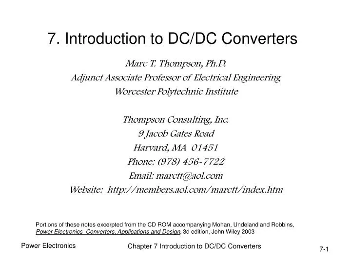
7. Introduction to DC/DC Converters. Marc T. Thompson, Ph.D. Adjunct Associate Professor of Electrical Engineering Worcester Polytechnic Institute Thompson Consulting, Inc. 9 Jacob Gates Road Harvard, MA 01451 Phone: (978) 456-7722 Email: marctt@aol.com

E N D
7. Introduction to DC/DC Converters Marc T. Thompson, Ph.D. Adjunct Associate Professor of Electrical Engineering Worcester Polytechnic Institute Thompson Consulting, Inc. 9 Jacob Gates Road Harvard, MA 01451 Phone: (978) 456-7722 Email: marctt@aol.com Website: http://members.aol.com/marctt/index.htm Portions of these notes excerpted from the CD ROM accompanying Mohan, Undeland and Robbins, Power Electronics Converters, Applications and Design, 3d edition, John Wiley 2003 Chapter 7 Introduction to DC/DC Converters
Summary • Non-isolated (i.e. no transformer) DC/DC converters Chapter 7 Introduction to DC/DC Converters
Block Diagram of Typical AC Input, Regulated DC Output System Chapter 7 Introduction to DC/DC Converters
Stepping Down a DC Voltage • In this example, the average value of the output voltage = DVin where D is the DUTY CYCLE in PWM (pulse-width modulation) control • D = ton/Ts Chapter 7 Introduction to DC/DC Converters
Step-Down (Buck) DC-DC Converter • Add LC filter to reduce switching ripple • Flyback diode also needed Chapter 7 Introduction to DC/DC Converters
Buck Converter: Waveforms • Steady state; inductor current flows continuously • Waveform below for buck in continuous conduction mode Chapter 7 Introduction to DC/DC Converters
Buck Converter: SPICE Circuit • Circuit shown: fsw = 200 kHz, D = 0.5 Chapter 7 Introduction to DC/DC Converters
Buck Converter: Startup Waveforms Chapter 7 Introduction to DC/DC Converters
Analysis for DC/DC Converter in Continuous Conduction and Steady State • In steady state, the inductor current returns to the same value every switching cycle, or every T seconds • Therefore, the inductor ripple current UP equals ripple DOWN • Several assumptions to simplify analysis: • Periodic steady state --- all startup transients have died out • Small ripple --- ripple is small compared to average values Chapter 7 Introduction to DC/DC Converters
Buck Converter in Continuous Conduction • In continuous conduction, buck converter has 2 states --- switch OPEN and switch CLOSED Switch closed (for time DT) Switch open (for time (1-D)T) Chapter 7 Introduction to DC/DC Converters
Buck Converter in Continuous Conduction • The inductor ripple current UP equals ripple DOWN • We already knew this result from first principles, but this methodology of inductor Volt-second balance can be used to evaluate other more complicated DC/DC converters Chapter 7 Introduction to DC/DC Converters
Buck Converter: Waveforms at the Boundary of Cont./Discont. Conduction • ILB = critical current below which inductor current becomes discontinuous Chapter 7 Introduction to DC/DC Converters
Buck Converter: Discontinuous Conduction Mode • Steady state; inductor current discontinuous (i.e. it goes zero for a time) • Note that output voltage depends on load current Chapter 7 Introduction to DC/DC Converters
Buck: Limits of Discontinuous Conduction • The duty-ratio of 0.5 has the highest value of the critical current • For low output current, buck goes discontinuous Chapter 7 Introduction to DC/DC Converters
Buck: Limits of Cont./Discont. Conduction • In regulated power supply, Vd may fluctuate but Vo is kept constant by control of D Chapter 7 Introduction to DC/DC Converters
Buck Conv.: Output Voltage Ripple • ESR is assumed to be zero; continuous conduction mode Chapter 7 Introduction to DC/DC Converters
Buck Conv.: Output Voltage Ripple • ESR is assumed to be zero Chapter 7 Introduction to DC/DC Converters
Buck Conv.: Calculations • Shown for SPICE example with fsw = 200 kHz, D = 0.5, L = 33 µH, C = 10 µF, Io = 1A Chapter 7 Introduction to DC/DC Converters
Buck: SPICE Result in Periodic Steady State • Analysis shows inductor ripple = 0.38 A-pp, output voltage ripple = 24 mV-pp, confirmed by SPICE Chapter 7 Introduction to DC/DC Converters
Pulse-Width Modulation (PWM) in DC-DC Converters Chapter 7 Introduction to DC/DC Converters
Step-Up (Boost) DC-DC Converter • Output voltage must be greater than the input Chapter 7 Introduction to DC/DC Converters
Boost Converter Waveforms • Continuous current conduction mode Switch closed: Switch open: Inductor Volt-second balance: Chapter 7 Introduction to DC/DC Converters
Boost: Limits of Cont./Discont. Conduction • The output voltage is held constant • For low load current, current conduction becomes discontinuous Chapter 7 Introduction to DC/DC Converters
Boost Converter: Discont. Conduction • Occurs at light loads Chapter 7 Introduction to DC/DC Converters
Boost: Limits of Cont./Discont. Conduction • The output voltage is held constant Chapter 7 Introduction to DC/DC Converters
Boost Converter: Effect of Parasitics • The duty-ratio D is generally limited before the parasitic effects become significant Chapter 7 Introduction to DC/DC Converters
Boost Converter Output Ripple • ESR is assumed to be zero • Assume that all the ripple component of diode current flows through capacitor; DC component flows through resistor Chapter 7 Introduction to DC/DC Converters
Step-Down/Up (Buck-Boost) Converter • The output voltage can be higher or lower than the input voltage • Note output phase inversion Chapter 7 Introduction to DC/DC Converters
Buck-Boost Converter: Waveforms • Continuation conduction mode Switch closed: Switch open: Inductor Volt-second balance: Chapter 7 Introduction to DC/DC Converters
Buck-Boost: Limits of Cont./Discont. Conduction • The output voltage is held constant Chapter 7 Introduction to DC/DC Converters
Buck-Boost: Discontinuous Conduction • This occurs at light loads Chapter 7 Introduction to DC/DC Converters
Buck-Boost Converter: Limits of Cont./Discont. Conduction • The output voltage is held constant Chapter 7 Introduction to DC/DC Converters
Buck-Boost Converter: Effect of Parasitics • The duty-ratio is limited to avoid these parasitic effects from becoming significant Chapter 7 Introduction to DC/DC Converters
Buck-boost Converter: Output Voltage Ripple • ESR is assumed to be zero Chapter 7 Introduction to DC/DC Converters
Cuk DC-DC Converter • The output voltage can be higher or lower than the input voltage • Capacitor C1 is primary means of storing and transferring energy from input to output • When switch is ON, C1 discharges through the switch and transfers energy to the output • When switch is OFF, capacitor C1 is charged through the diode by energy from the input and L1 Chapter 7 Introduction to DC/DC Converters
Cuk DC-DC Converter: Waveforms • The capacitor voltage is assumed constant (very large) • Note phase inversion at the output Chapter 7 Introduction to DC/DC Converters
SEPIC Converter • Single-ended primary inductance converter (SEPIC) • Can buck or boost the voltage • Note that output is similar to buck-boost, but without a phase inversion Chapter 7 Introduction to DC/DC Converters
Converter for DC-Motor Drives • Four quadrant operation is possible • For: • DC motor drives • DC to AC inverters for UPS Chapter 7 Introduction to DC/DC Converters
Converter Waveforms • Bi-polar voltage switching Chapter 7 Introduction to DC/DC Converters
Converter Waveforms • Uni-polar voltage switching Chapter 7 Introduction to DC/DC Converters
Output Ripple in Converters for DC-Motor Drives • Bi-polar and uni-polar voltage switching Chapter 7 Introduction to DC/DC Converters
Switch Utilization in DC-DC Converters • It varies significantly in various converters • PT = VTIT where VT and IT are peak switch voltage and current • In direct converters (buck and boost) switch utilization is good; in indirect converter (buck-boost and Cuk) switch utilization is poor Chapter 7 Introduction to DC/DC Converters
Equivalent Circuits in DC-DC Converters • Replacing inductors and capacitors by current and voltage sources, respectively Chapter 7 Introduction to DC/DC Converters
Reversing the Power Flow in DC-DC Conv. • For power flow from right to left, the input current direction should also reverse Chapter 7 Introduction to DC/DC Converters
Real-World Issue: Capacitor ESR • Real-world capacitors have equivalent series resistance (ESR) • This ESR may have dominant effect on output ripple Chapter 7 Introduction to DC/DC Converters
Effects of Capacitor ESR • Without ESR, output ripple is 24 mV-pp • ESR has increased ripple to approximately 30 mV-pp Chapter 7 Introduction to DC/DC Converters