Download
1 / 26
260 likes | 293 Views
Explore surface emissivity challenges in modeling sea foam layer for WindSat retrieval with a physical model emphasizing foam emission components.

E N D
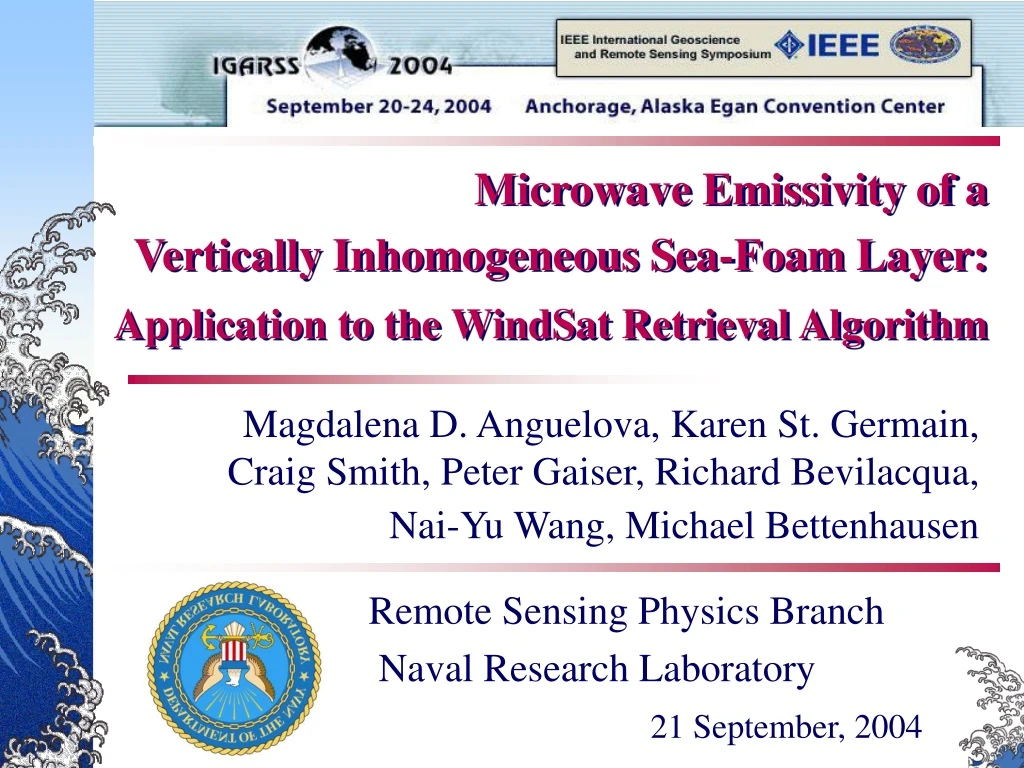
Microwave Emissivity of a Vertically Inhomogeneous Sea-Foam Layer:Application to the WindSat Retrieval Algorithm Magdalena D. Anguelova, Karen St. Germain, Craig Smith, Peter Gaiser, Richard Bevilacqua, Nai-Yu Wang, Michael Bettenhausen Remote Sensing Physics Branch Naval Research Laboratory 21 September, 2004
WindSat forward model • Radiative transfer equation: • Semi-empirical surface model: e = er + Δe • 2-scale model for er; • WindSat data for Δe.
Complete physical model • Surface emissivity: • Difficulties in modeling e: • Two-scale model limitations; • Limited knowledge for ef ; • Separate er and ef ; • High uncertainty for f ;
Whitecaps on the surface Bubble plumes below the surface Sea foam
ε' ε" 6.8 GHz 18.7 GHz 37.0 GHz Foam dielectric constant
air seawater Matching impedances
air seawater air foam (98%) foam (10%) seawater Matching impedances
F GHz λ0 cm λf cm fa= 98% λf cm fa= 10% 6.8 4.4 3.2 0.60 10.7 2.8 2.1 0.41 Tdown 18.7 1.6 1.31 0.28 23.8 1.3 1.1 0.26 37.0 0.8 0.72 0.20 Tsc Mechanisms of attenuation • Absorption: • 85%-90%; • Small in bubble walls; • Max at water boundary; • Scattering: • 10%-15%; • λ-dependent. Max bubble dia 2 cm Min bubble dia 0.02 cm
+ = + + + Foam-covered area TB • Reflection/scattering terms; • Emission terms. z = 0 z = -d TBf
Droppleman, 1970 Rosenkranz and Staelin, 1972 Raizer and colleagues 1982, 1992 Chen et al., 2003 Model requirements • Vertically inhomogeneous layer; • Absorption and scattering; • Various contributions to foam emission.
Our choice • Macro characteristics (layer); • Vertically inhomogeneous (depth profile); • Flat specular boundaries; • Incoherent approach -- weak scattering; • Ignore scattering term; z = 0 Air, ε0=1 Foam, ε (z) z = -d Water, ε
Foam emission components + diffuse scattering term dz
dz Foam emission components
dz Foam emission components
dz Foam emission components
+ = + + + Foam contributions d/0 0.02 d =0/50 320 m d/0= 0.25 d = 0/4 4 mm TBf0
Reising et al., 2002 TBf over distribution of thickness
Necessary experiments • Void fraction profile; • Values for boundary conditions; • Bubble size distribution; • Thickness distribution; • Azimuthal dependence.