Download
1 / 30
300 likes | 526 Views
Shot-profile migration of GPR data. Jeff Shragge, James Irving, and Brad Artman Geophysics Department Stanford University. Seismic vs. GPR Data. Seismic Elastic waves Multi-offset data Redundancy multiple offsets Localized source. GPR EM waves Single- or Multi-offset data

E N D
Shot-profile migration of GPR data Jeff Shragge, James Irving, and Brad Artman Geophysics Department Stanford University jeff@sep.stanford.edu
Seismic vs. GPR Data Seismic Elastic waves Multi-offset data Redundancy multiple offsets Localized source GPR EM waves Single- or Multi-offset data Redundancy repeated acquisition Localized source Seismic GPR paul@sep.stanford.edu
Seismic vs. GPR Data Our aim: Transfer recent advances in multi-offset seismic migration techniques to GPR Seismic GPR Common goal: Best possible image of subsurface reflectivity paul@sep.stanford.edu
Agenda • Rationale • Multi-offset, prestack, wave-equation imaging • Imaging assumptions • Methodology • Wavefield extrapolation • Shot-profile migration • Imaging condition • Angle-domain gathers • Field data example paul@sep.stanford.edu
Agenda • Rationale • Multi-offset, prestack, wave-equation imaging • Imaging assumptions • Methodology • Wavefield extrapolation • Shot-profile migration • Imaging condition • Angle-domain gathers • Field data example paul@sep.stanford.edu
Acquisition: Why Multi-offset? Pros Improved: velocity estimation, reflector imaging, S/N ratio Affords better subsurface characterization AVO/AVA studies, facies and property estimates • Vast majority of GPR work involves constant offset data • collection, processing, interpretation • Multi-offset systems are increasingly available jeff@sep.stanford.edu
Acquisition: Why Multi-offset? • Vast majority of GPR work involves constant offset data • collection, processing, interpretation • Multi-offset systems are increasingly available Cons • More labor intensive • Improving with new technology • More computationally intensive jeff@sep.stanford.edu
Processing: Why pre-stack wave-equation? • Pre-stack imaging is more robust • Post-stack migration assumes that NMO-transformed traces are a good approximation of the zero-offset trace • Significant lateral velocity variation breaks NMO approximation • Maintain angular information for AVA studies • Wave-equation migration is more accurate • No high-frequency approximation • Wave-based not ray-based • Accurate over full range of frequencies • Naturally handle multipathing (unlike Kirchhoff migration) jeff@sep.stanford.edu
Agenda • Rationale • Multi-offset, prestack, wave-equation imaging • Imaging assumptions • Methodology • Wavefield extrapolation • Shot-profile migration • Imaging condition • Angle-domain gathers • Field data example jeff@sep.stanford.edu
Imaging Assumptions Tx Rx • Maxwell’s equations represented by 2-D scalar wave equation • Assumptions • Geology is 2-D t x jeff@sep.stanford.edu
Imaging Assumptions • Maxwell’s equations represented by 2-D scalar wave equation • Assumptions • Geology is 2-D and data is collected perpendicular to strike (TE mode) Tx Rx t x jeff@sep.stanford.edu
Imaging Assumptions • Maxwell’s equations represented by 2-D scalar wave equation • Assumptions • Geology is 2-D and data is collected perpendicular to strike (TE mode) • Heterogeneities in earth are small such that gradients in EM constitutive parameters are negligible • Isotropic scattering, no antenna radiation patterns Tx Rx t x jeff@sep.stanford.edu
Governing Equations Governing 2-D scalar wave-equation in frequency (ω) domain E= Electric field (component) v(x,z)= wavespeed ε= dielectric permittivity μ = magnetic permeability σ= conductivity c = speed of light i = sqrt(-1) jeff@sep.stanford.edu
Agenda • Rationale • Multi-offset, prestack, wave-equation imaging • Imaging assumptions • Methodology • Wavefield extrapolation • Shot-profile migration • Imaging condition • Angle-domain gathers • Field data example jeff@sep.stanford.edu
Wavefield Extrapolation Wavefield propagates by advection - with solution Want solution to Helmholtz equation given boundary condition E(x,t,z=0) Wave-equation dispersion relation jeff@sep.stanford.edu
Shot-profile Migration • Directly mimics the experiment by migrating the shot-record • Define source and receiver wavefields • Source wavefield – Ss(x,t,z=0) • Idealized point source at Tx location • Propagated causally: exp(ikzΔz) • Subscript sis the Shot-profile index • Receiver wavefield - Rs(x,t,z=0) • Rx multi-offset data from point source at Tx location • Propagated acausally: exp(-ikzΔz) • Subscript s is the Shot-profile index jeff@sep.stanford.edu
Shot-profile Migration x x t t • Seed source and receiver wavefields At Z=0 Source Receiver jeff@sep.stanford.edu
Shot-profile Migration x x t t • Seed source and receiver wavefields • Propagate S and R to all depths using wavefield extrapolation At Z=nΔZ Source Receiver jeff@sep.stanford.edu
Shot-profile Migration • Correlate Ss and Rs using imaging condition • Repeat for all shot profiles and sum jeff@sep.stanford.edu
Angle-domain Gathers • Compute image domain equivalent of offset: h • Have to use more advanced imaging condition • Reflectivity at opening angle γ computed after imaging • kh= offset wavenumber kz = vertical wavenumber • Velocity Analysis: angle gathers are flat for correct velocity jeff@sep.stanford.edu
Agenda • Rationale • Multi-offset, prestack, wave-equation imaging • Imaging assumptions • Methodology • Wavefield extrapolation • Shot-profile migration • Imaging condition • Angle-domain gathers • Field data example jeff@sep.stanford.edu
Field Data Example • 2-D multi-offset GPR data set - Vancouver, BC, Canada • Geology • Sand and gravel glacial outwash deposit • Underlain by conductive marine clay with topographically varying surface • Data Acquisition • PulseEkko 100 GPR system • 100 MHz antennas oriented perpendicular to survey line • 30 receivers/shot gather: 0.5m-15m at 0.5m intervals • 200 shot gathers at 0.5m shot spacing jeff@sep.stanford.edu
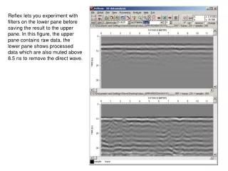
Unmigrated near-offset section Layering? Top of Clay? Diffractions • Velocity model generated using semblance analysis on CMP gathers • RMS velocity picks converted into an interval velocity function • Water table ~ 4.5 meters jeff@sep.stanford.edu
Migrated near-offset section jeff@sep.stanford.edu
Unmigrated near-offset section jeff@sep.stanford.edu
Migrated near-offset section On-lap reflectors Reflector Continuity Top of Clay Collapsed Hyperbolas • Clearer image after hyperbola collapse • More laterally continuous reflectors • Top of clay readily identifiable • On-lap reflectors in sand/gravel layer visible jeff@sep.stanford.edu
Flat Angle Gathers jeff@sep.stanford.edu
Extensions Antenna radiation patterns • Flexibility of Shot-profile allows for radiation patterns to be modeled into wavefields Non-acoustic propagation • Wavefield extrapolation does not require acoustic propagation; apply more physical operators Anisotropic scattering • Angle gathers preserve the reflection angle information • Compensate with anisotropic scattering angle filters jeff@sep.stanford.edu
Conclusions • Prestack wave-equation methods can be extended to GPR data • Shot-profile migration is flexible • Incorporate radiation patterns in source and receiver wavefields • Incorporate more realistic scattering physics into imaging condition jeff@sep.stanford.edu
Acknowledgements • Rosemary Knight • Stanford Environmental Geophysics • Biondo Biondi • Stanford Exploration Project jeff@sep.stanford.edu