Download
1 / 11
110 likes | 329 Views
Lecture #7 EGR 110 – Engineering Graphics. Reading Assignment: Ch. J in Engineering Graphics Workbook, Series 1.2 or Series 2 Sketching Assignment: Sketching Assignment #6. Sectional Views

E N D
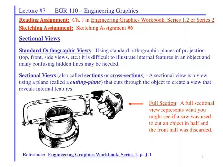
Lecture #7 EGR 110 – Engineering Graphics Reading Assignment:Ch. J in Engineering Graphics Workbook, Series 1.2 or Series 2 Sketching Assignment:Sketching Assignment #6 Sectional Views Standard Orthographic Views - Using standard orthographic planes of projection (top, front, side views, etc.) it is difficult to illustrate internal features in an object and many confusing hidden lines may be needed. Sectional Views (also called sections or cross-sections) - A sectional view is a view using a plane (called a cutting-plane) that cuts through the object to create a view that reveals internal features. Full Section: A full sectional view represents what you might see if a saw was used to cut an object in half and the front half was discarded. Reference: Engineering Graphics Workbook, Series 1, p. J-1
Lecture #7 EGR 110 – Engineering Graphics Creating a section view: 1) A cutting plane passes through the object, cutting the object in half (for a full section) 2) Remove the cutting place and pull the two halves apart 3) Discard the front half. Add section lines to indicate where material was cut by the cutting plane. Reference: Engineering Graphics Workbook, Series 1, p. J-2
Lecture #7 EGR 110 – Engineering Graphics Add additional visible lines as needed to represent the back edges of the half cylinders. Cutting-plane lines are used in a view adjacent to the sectioned view to show the location of the cut and includes arrow indicating the direction of sight for the sectioned view. Imagine where the material was cut by the cutting plane. Sketch these areas and fill them with section lines. Add center lines as needed. Reference: Engineering Graphics Workbook, Series 1, p. J-2
Lecture #7 EGR 110 – Engineering Graphics Two new types of lines are introduced with sections: Section lines – Section lines are used over the surface of all areas that are in contact with the cutting plane. If you envision cutting the object in half, then section lines appear over all surfaces that were cut. Example: Section lines inside a rectangular area Cutting plane line – A cutting plane line is used to show the edge view (EV) of the cutting plane. It is always shown in a view that is adjacent to the sectioned view. Arrows are included on the ends of the cutting plane lines to indicate the line of sight.
Lecture #7 EGR 110 – Engineering Graphics • 3 primary types of sectional views: (briefly discuss each) • full section – the cutting plane passes entirely through the object • half section – the cutting place only passes half way through an object (so one half of a view will the sectioned and the other half will not) • broken-out section – an irregular cut is used to expose certain internal features Note: Hidden lines are generally omitted from the sectioned view when using full sections. Example: Sketch a simple block of wood that has a counterbored hole. Draw the top view and the front view in full section. Include the cutting-plane line.
Incorrect Correct Lecture #7 EGR 110 – Engineering Graphics Rules for cutting-plane lines: 1) Cutting-plane lines have precedence over other line types (such as visible, hidden, and center lines). 2) A cutting-plane line should be used in a view that is adjacent to the sectioned view. The cutting-plane line represents the edge-view (EV) of the plane that cuts the object to form the section. 3) The arrow(s) on the cutting-plane line represent the direction of sight. Rules for section lines: 1) Section lines are thin, dark, parallel lines that fill an area cut by the cutting plane. 2) Section lines should be at the same angle for all sectioned areas made of the same material. Example: Show correct and incorrect section lines in the figures below.
Lecture #7 EGR 110 – Engineering Graphics Rules for section lines (continued): 3) There are different types of section lines for different types of materials. If no material is specified, ANSI-31 is often used as a default. Example: Section lines for various types of materials are shown below. Reference: Engineering Graphics Workbook, Series 1, p. J-3
Incorrect Correct Lecture #7 EGR 110 – Engineering Graphics Rules for section lines (continued): 4) Different section line angles are often used for different materials. Example: The top area is cast iron and the bottom area is brass. Show correct and incorrect section lines in the figures below. Example: Section lines for various types of materials are shown below. Note that different angles are used since the materials are adjacent. Reference: Engineering Graphics Workbook, Series 1, p. J-3
Incorrect Correct Incorrect Incorrect Incorrect Correct Lecture #7 EGR 110 – Engineering Graphics Rules for section lines (continued): 5) Avoid section lines that are parallel or perpendicular to visible lines in the object. Example: Show correct and incorrect section lines in the figures below. 6) Sectioned areas are always completely bounded by visible lines. Example: Show correct and incorrect sectioned areas.
Lecture #7 EGR 110 – Engineering Graphics Sectioned Pictorials: Sectioned objects are sometimes illustrated using pictorials (isometrics, typically). Several of the homework problems in this chapter require sectioned isometrics. Example: Reference: Engineering Graphics Workbook, Series 1, p. J-9
Front Lecture #7 EGR 110 – Engineering Graphics Example: Draw the top view and the front view in full section. Also sketch a sectioned pictorial (isometric) of the object.