Download
1 / 9
90 likes | 110 Views
Explore the innovative technology behind the JCMT SCUBA-2 imaging system, requiring large-format detector arrays and sophisticated signal readouts. This advanced technology allows for wider coverage and higher pixel resolution for submillimeter astronomy. Learn how bolometers and SQUID amplifiers work in detecting and analyzing incoming signals, enabling high-quality imaging capabilities for astronomical observations. Discover the intricate processes involved in constructing and cooling the detectors to ultra-low temperatures for optimal performance.

E N D
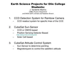
SCUBA-2 technology To fill an 88 arcmin field-of-view of the JCMT requires many thousands of pixels! Conventional bolometer technology is impractical! We need: the ability to construct large format detector arrays signal readouts that can be multiplexed
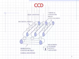
Deep-etched trench (10 μm) 1.135 mm 1.135mm Detector Wafer SQUID MUX Wafer Bump bond TES Nitride membrane (0.5 μm) TES on SiN membrane Si brick l/4 thick SQUID mux backplane Pixel geometry Indium bump bonds Quarter-wave Si Brick Detector cooled to 100mK Time division multiplexing based on SQUID amplifier Mux is formed by columns of SQUIDS connected in series Address line turns on each row of SQUIDS Not to scale
2 temperature time Bolometers: Basic principles • Two components: A sensitive thermometer and high cross-section absorber • Thermometer and absorber • are connected by a weak thermal • link to a heat sink • Incoming photon is converted to heat in the absorber: • T = T T0 = E/C • Temperature rise decays as power in absorber flows out to the heat sink • Bolometer temperature is proportional to the incoming power
Resistance I RN SQUID Amplifier RC Bias point R(T) TES Tc Temperature V bias Transition edge sensors • Voltage-biased on normal-superconducting transition • Resistance is a very steep dependence on temperature in transition region • Film held at constant voltage bias - change in resistance results in a change in current through the film • Low noise, low power (~ 1nW) SQUID ammeter readout • Disadvantage: There is a fixed amount of power a device can handle
SCUBA-2 focal planes Key features include: • Superconducting transition edge sensors • SQUID multiplexer readouts • 4 × 1280 pixel sub-arrays in each focal plane • 100mK operation using liquid cryogen-free dilution refrigerator
Cold electronics module Magnetically sensitive SSA module pcb High density connections to woven cables to room temp Ceramic ‘batwing’ pcb Niobium flexis Hot bar reflowed
Detector subassembly and readout • The TES wafer bump • bonded to the SQUID • multiplexer Glue writer depositing • epoxy on individual tines • Detector wire • bonded to ceramic • batwing PCB Detector array on the epoxy bonding machine During attachment of the Be/Cu hairbrush completed subassembly Woven ribbon cables takes signals from 1K to 300K Batwing PCB connected to the SSA amplifier board via superconducting niobium flexible circuits using hot bar reflow technique SQUID amplifiers Multichannel Readout Electronics Subassembly and readout
COST SCUBA-2 is the first large-format CCD-style imager for submillimetre astronomy Interesting Facts: Instrument No. of pixels Map speed Cost per pixel UKT14 1 1 $700,000 SCUBA 128 7000 $ 70,000 SCUBA-2 12800 1,000,000+ $ 875