Download
1 / 51
530 likes | 809 Views
Semiconductor devices and opto-electronics. Meint Smit Leon Kaufmann Xaveer Leijtens. Opto-Electronic Devices Group Eindhoven University of Technology. Course information. Opto-electronics: Book: Gerd Keiser, Optical Fiber Communications 3rd edition, McGraw-Hill, obligatory!

E N D
Semiconductor devices and opto-electronics Meint Smit Leon Kaufmann Xaveer Leijtens Opto-Electronic Devices Group Eindhoven University of Technology
Course information • Opto-electronics: • Book: Gerd Keiser, Optical Fiber Communications 3rd edition, McGraw-Hill, obligatory! • Contact: Xaveer Leijtensx.j.m.leijtens@tue.nl 040 – 247 5112 • Electronic devices: • Book: Linda Edwards-Shea, The Essence of Solid- State Electronics, Prentice Hall, obligatory! • Contact: Leon Kaufmannl.m.f.kaufmann@tue.nl 040 – 247 5801 • Website: http://oed.ele.tue.nl (education)
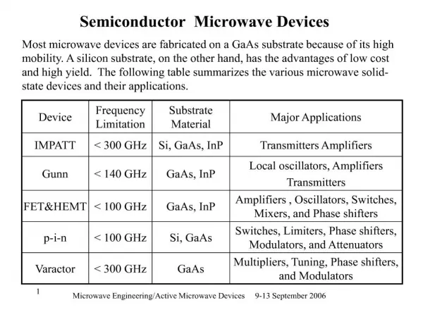
Contents semiconductor devices • Recapitulation: electrons in atoms, introduction to quantum mechanics • Solid state materials: crystal structures, energy band diagrams of insulators, metals and (un)doped semiconductors • Semiconductors and carrier transport • Principle of operation of pn junction diodes • Fundamentals of MOSFETs • CMOS technology (incl. video demonstration)
OGO3.2Free space optical communication Kickoff Meeting Dec 1 in MA1.41 13:30h
Examination • Closed-book examination, formula sheet will be provided • Electronic devices: Edwards-Shea, chapter 1-8 • Opto-electronics: Keiser
TRANSMITTER RECEIVER – – – + + Optical communication FIBRE
Electromagnetic spectrum • Optical communication wavelength: = 1500 nmcorresponds to = c/ 200 THz = 200.000 GHz • 1% = 2 THz = 2000 GHz • EDFA-bandwidth 30 nm 4 THz
Fiber core SiO2+ GeO2 Ø 10 mm n 1.443 SiO2 Cladding Ø 125 mm n 1.44 Primary coating (soft) Ø 400 mm Secondary coating (hard) Ø 1 mm Standard Single-Mode (SM) Fiber
– – Optical source TRANSMITTER FIBER Performance Modulation speed Fiber-coupled power +
– Light Emitting Diode (LED) + Typical performance data Power in MM-fiber: 100 mW Power in SM-fiber: 1 mW Direct Modulation Bandwidth: 100MHz
Laser Typical performance Power (in fiber): 5-10 mW Max: 100-300 mW Direct Modulation Bandwidth: 1-10 GHz
+ – Photodiode detector Typical performance data Responsivity: ~1 mA / mW Bandwidth: 1-20 GHz
First Generation, ~1975, 0.8 mm MM-fiber, GaAs-laser or LED Second Generation, ~1980, 1.3 mm, MM & SM-fiber InGaAsP FP-laser or LED Third Generation, ~1985, 1.55 mm, SM-fiber InGaAsP DFB-laser, ~ 1990 Optical amplifiers Fourth Generation, 1996, 1.55 mm WDM-systems 0.8 0.9 1.0 1.1 1.2 1.3 1.4 1.5 1.6 1.7 1.8 Wavelength (mm) Optical communication systems 2 dB/cm Attenuation
optical fiber optical receiver optical transmitter Multiwavelength Transmitter Multiwavelength Receiver MUX DMX WDM-transmission
Er-doped fiber PUMP LASER 0.98 mm or 1.48 mm MUX FILTER Erbium-Doped Fiber Amplifier (EDFA)
Synchronous Digital Hierarchy Europe SDH: Synchronous Digital Hierarchy STM: Synchronous Transport Module US & Japan SONET: Synchronous Optical Network OC: Optical Carriers
(10x / 2.5 yrs) 5 yrs Trunk transmission capacity WDM experiments ETDM Si electronics installed (10x / 6 yrs)
1 Tb/s 100 Gb/s 256 ‘04? ‘80 ‘00 ‘86 ‘97 ‘89 ‘83 ‘96 • • • • • • • • ‘99 • 10 Gb/s 64 ‘98 • # WDM-channels 1 Gb/s 16 0.1 Gb/s 4 ‘98 • 1 0.01 0.1 1 10 100 Channel bitrate (Gb/s) Trunk transmission capacity
< 10000 km < 10 Tbit/s Global Network Wide Area Network < 100 km < 1 Tbit/s Metropolitan/Regional Area Optical Network FTTB Client/Access Networks ATM < 20 km 100M - 10 Gbit/s ISP Cable modem Networks SDH/ SONET Gigabit Ethernet ATM FTTH Corporate/ Enterprise Clients Cable PSTN/IP Mobile Courtesy: A.M.J. Koonen Optical Transport Network
1 1 in out 2 2 X X X X Integrated optical cross-connect Dimensions: 8x12 mm2
Fibre propagation n1 n2
z=0 z=L Attenuation z=0 z=L Dispersion Fiber performance
1000 CVD (Chemical Vapor Deposition) 100 Attenuation (dB/km) 10 • 20 dB/km (Corning) 1 0.16 dB/km 0.1 1960 1970 1980 1990 2000 Optical attenuation in glass
IR band edge Rayleigh scattering 1.5 UV absorption 1.0 Attenuation (dB/km) OH--peak 0.5 0.16 dB/km 0.2 0.6 0.7 0.8 0.9 1.0 1.1 1.2 1.3 1.4 1.5 1.6 1.7 1.8 Wavelength (mm) Fiber attenuation (SiO2)
A note on dB and dBm • dB • optical signals: • electrical signals: • dBm • absolute power value (with 1 mW as reference) • power level in dBm: electrical dB = 2 x optical dB
n2<n1 2 n2<n1 n2<n1 2 1 1 1= c 1 >c 1 c n1 n1 n1 Snell’s law Critical angle Total internal reflection Reflection & refraction
Multimode fiber Critical angle: n0 n0 n2 0 n1 Maximum entrance angle: c Numerical aperture: Numerical Aperture
L c n1 n2 t Dispersion (intermodal)
dBe 0 3 6 dBo 0 1.5 3 t FWHM n DT t D o De Rule of thumb: Bandwidth (incoherent) Cross talk Bandwidth and bit rate
SM Single-Mode MM-SI Multi-Mode Step Index MM-GI Multi-Mode Graded Index Fiber types refractive index
Fiber classification (1) MM-SI: Multi Mode - Step Index fiber Core diameter 50 - 400 m Cladding 125 (500) m 2nd coating 250 - 1000 m NA 0.16 - 0.5 Attenuation 1 - 4 dB/km Bandwidth 6 - 25 MHz.km Application Short distance, low cost limited bandwidth
Fiber classification (2) MM-GI: Multi Mode - Graded Index fiber Core diameter 50 m standard Cladding 125 m 2nd coating 200-1000 m NA 0.2 - 0.3 Attenuation 1 dB/km (1300 nm) Bandwidth 150 MHz.km - 2 GHz.km Application Medium distance communication LED/Laser sources
Fiber classification (3) SM-SI: Single Mode - Step Index fiber Core diameter 3-10 m Cladding 50-125 m 2nd coating 200-1000 m NA ~0.1 (not used) Attenuation 0.20@1550 - 0.4@1300 dB/km Bandwidth >> 500 MHz.km Application Long distance communication Lasers, standard fiber
The wave equation Solutions to Maxwell’s equations: phase fronts Plane wave: Spherical wave:
kx k kx kz kz x x z z Wave vector and decomposition
kx phase fronts k+ x absorber kx+ metallic plates x + kz kz z - kx- k- z Interference
metallic plates x kz d z The metallic waveguide
2 1 0 waveguide d m=0 m=1 m=2 Modes & Rays
c2 kx substrate modes superstrate modes n1k0 c0 m=4 m=3 m=2 guided modes m=1 m=0 kz n2k0 n0k0 n1k0 n2 n1 n0 m=4 m=0 m=1 m=2 m=3 Optical waveguide modes
d 0 1 2 a Mode intensity profiles • Optical modes: • Excitation of modes: Planar: Single-mode if V Fiber: Single-mode if V 2.405
V-parameter • V number: determines how many modes a fiber supports • Lowest order mode HE11 has no cut-off • Single-mode fiber:
Number of modes • Number of modes in step-index fiber • Optical power in the cladding for large values of V
n1 HE11 TE01 TM01 EH11 HE31 HE12 n2 0 1 2 3 4 5 6 Step index fiber modes (2) Effective index b/k as a function of Single-mode fiber: V 2.405
Birefringence • HE11: • Birefringence: difference in effective refractive indices between two polarization modes • Fiber beat length: phase difference between the two polarization modes is Vertical mode Horizontal mode
Fiber materials • Silica glass fiber • starting material: pure silica (SiO2) in the form of fused quartz (amorphous) • modification of refractive index by addition of impurities • lowering refractive index : B2O3, F • raising refractive index : P2O5, GeO2 • Polymer optical fiber (POF) • large core (multimode) • large refractive index difference between core and cladding • easy handling • relatively high losses
Losses in polymer optical fiber • Absorption loss in POF >>> Absorption loss in Silica fiber search for low loss polymers • PMMA (Poly Methyl Metacrylate) • PS (Polystyrene) • FA (Fluoro acrylate) • Typical absorption levels: 100 dB/km • Low loss windows: several windows in the range 500-800 nm • New material development: perfluorinated polymer 50 dB/km from visible to 1600 nm • Core type • Step index • Graded index