Download
1 / 37
370 likes | 383 Views
Explore the principles, services, and technologies of the network layer, including routing algorithms, IPv4 and IPv6 protocols, virtual circuits, datagram networks, ICMP, and router architecture. Gain insights into forwarding, routing, and the interplay between these essential network layer functions.

E N D
1DT057Distributed Information SystemChapter 4Network Layer Introduction
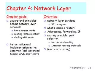
Chapter 4: Network Layer Chapter goals: • understand principles behind network layer services: • network layer service models • forwarding versus routing • how a router works • routing (path selection) • dealing with scale • advanced topics: IPv6, mobility • instantiation, implementation in the Internet Network Layer
Chapter 4: Network Layer • 4. 1 Introduction • 4.2 Virtual circuit and datagram networks • 4.3 What’s inside a router • 4.4 IP: Internet Protocol • Datagram format • IPv4 addressing • IPv6 Network Layer
Two Key Network-Layer Functions • forwarding: move packets from router’s input to appropriate router output • routing: determine route taken by packets from source to dest. • routing algorithms analogy: • routing: process of planning trip from source to dest • forwarding: process of getting through single interchange Network Layer
routing algorithm local forwarding table header value output link 0100 0101 0111 1001 3 2 2 1 value in arriving packet’s header 1 0111 2 3 Interplay between routing and forwarding Network Layer
Chapter 4: Network Layer • 4. 1 Introduction • 4.2 Virtual circuit and datagram networks • 4.3 What’s inside a router • 4.4 IP: Internet Protocol • Datagram format • IPv4 addressing • ICMP • IPv6 Network Layer
Network layer connection and connection-less service • datagram network provides network-layer connectionless service • VC network provides network-layer connection service Network Layer
Virtual circuits • each packet carries VC identifier (not destination host address) • every router on source-dest path maintains “state” for each passing connection • link, router resources (bandwidth, buffers) may be allocated to VC (dedicated resources = predictable service) “source-to-dest path behaves much like telephone circuit” • performance-wise • network actions along source-to-dest path Network Layer
VC number 22 32 12 3 1 2 interface number Incoming interface Incoming VC # Outgoing interface Outgoing VC # 1 12 3 22 2 63 1 18 3 7 2 17 1 97 3 87 … … … … Forwarding table Forwarding table in northwest router: Network Layer Routers maintain connection state information!
application transport network data link physical application transport network data link physical VIRTUAL CIRCUITS: SIGNALING PROTOCOLS • used in ATM, frame-relay, X.25 • not used in today’s Internet Network Layer 6. Receive data 5. Data flow begins 4. Call connected 3. Accept call 1. Initiate call 2. incoming call
application transport network data link physical application transport network data link physical DATAGRAM NETWORKS • no call setup at network layer • routers: no state about end-to-end connections • no network-level concept of “connection” • packets forwarded using destination host address • packets between same source-dest pair may take different paths Network Layer 1. Send data 2. Receive data
Forwarding table 4 billion possible entries Destination Address RangeLink Interface 11001000 00010111 00010000 00000000 through 0 11001000 00010111 00010111 11111111 11001000 00010111 00011000 00000000 through 1 11001000 00010111 00011000 11111111 11001000 00010111 00011001 00000000 through 2 11001000 00010111 00011111 11111111 otherwise 3 Network Layer
Longest prefix matching Prefix MatchLink Interface 11001000 00010111 00010 0 11001000 00010111 00011000 1 11001000 00010111 00011 2 otherwise 3 Examples Network Layer Which interface? DA: 11001000 00010111 00010110 10100001 Which interface? DA: 11001000 00010111 00011000 10101010
Chapter 4: Network Layer • 4. 1 Introduction • 4.2 Virtual circuit and datagram networks • 4.3 What’s inside a router • 4.4 IP: Internet Protocol • Datagram format • IPv4 addressing • IPv6 Network Layer
ROUTER ARCHITECTURE OVERVIEW Two key router functions: • run routing algorithms/protocol (RIP, OSPF, BGP) • forwarding datagrams from incoming to outgoing link Network Layer
Chapter 4: Network Layer • 4. 1 Introduction • 4.2 Virtual circuit and datagram networks • 4.3 What’s inside a router • 4.4 IP: Internet Protocol • Datagram format • IPv4 addressing • IPv6 Network Layer
ICMP protocol • error reporting • router “signaling” • IP protocol • addressing conventions • datagram format • packet handling conventions • Routing protocols • path selection • RIP, OSPF, BGP forwarding table THE INTERNET NETWORK LAYER Host, router network layer functions: Transport layer: TCP, UDP Network layer Network Layer Link layer physical layer
Chapter 4: Network Layer • 4. 1 Introduction • 4.2 Virtual circuit and datagram networks • 4.3 What’s inside a router • 4.4 IP: Internet Protocol • Datagram format • IPv4 addressing • IPv6 Network Layer
IP protocol version number 32 bits total datagram length (bytes) header length (bytes) type of service head. len ver length for fragmentation/ reassembly fragment offset “type” of data flgs 16-bit identifier max number remaining hops (decremented at each router) upper layer time to live header checksum 32 bit source IP address 32 bit destination IP address upper layer protocol to deliver payload to Options (if any) data (variable length, typically a TCP or UDP segment) IP DATAGRAM FORMAT Network Layer
IP FRAGMENTATION & REASSEMBLY • network links have MTU (max.transfer size) • largest possible link-level frame. • large IP datagram divided (“fragmented”) within net • one datagram becomes several datagrams • “reassembled” only at final destination • IP header bits used to identify, order related fragments fragmentation: in: one large datagram out: 3 smaller datagrams reassembly
Chapter 4: Network Layer • 4. 1 Introduction • 4.2 Virtual circuit and datagram networks • 4.3 What’s inside a router • 4.4 IP: Internet Protocol • Datagram format • IPv4 addressing • IPv6 Network Layer
223.1.1.2 223.1.2.2 223.1.3.27 223.1.3.1 223.1.3.2 223.1.2.1 IP ADDRESSING: INTRODUCTION 223.1.1.1 • IP address: 32-bit identifier for host, router interface • interface: connection between host/router and physical link • router’s typically have multiple interfaces • host typically has one interface • IP addresses associated with each interface 223.1.2.9 223.1.1.4 223.1.1.3 Network Layer 223.1.1.1 = 11011111 00000001 00000001 00000001 223 1 1 1
Subnets 223.1.1.1 • IP address: • subnet part (high order bits) • host part (low order bits) • What’s a subnet ? • device interfaces with same subnet part of IP address • can physically reach each other without intervening router 223.1.2.1 223.1.1.2 223.1.2.9 223.1.1.4 223.1.2.2 223.1.1.3 223.1.3.27 subnet Network Layer 223.1.3.2 223.1.3.1 network consisting of 3 subnets
223.1.1.0/24 223.1.2.0/24 223.1.3.0/24 Subnets • To determine the subnets, detach each interface from its host or router, creating islands of isolated networks. Each isolated network is called a subnet. Network Layer Subnet mask: /24
Subnets 223.1.1.2 223.1.1.1 223.1.1.4 How many? 223.1.1.3 223.1.7.0 223.1.9.2 Network Layer 223.1.9.1 223.1.7.1 223.1.8.1 223.1.8.0 223.1.2.6 223.1.3.27 223.1.2.1 223.1.2.2 223.1.3.1 223.1.3.2
host part subnet part 11001000 0001011100010000 00000000 200.23.16.0/23 IP addressing: CIDR CIDR:Classless InterDomain Routing • subnet portion of address of arbitrary length • address format: a.b.c.d/x, where x is # bits in subnet portion of address Network Layer
IP ADDRESSES: HOW TO GET ONE? Q: How does a host get IP address? • hard-coded by system admin in a file • Windows: control-panel->network->configuration->tcp/ip->properties • UNIX: /etc/rc.config • DHCP:Dynamic Host Configuration Protocol: dynamically get address from as server • “plug-and-play” Network Layer
E B A DHCP: Dynamic Host Configuration Protocol Goal: allow host to dynamically obtain its IP address from network server when it joins network • Allows reuse of addresses 223.1.2.1 DHCP 223.1.1.1 server Network Layer 223.1.1.2 223.1.2.9 223.1.1.4 223.1.2.2 arriving DHCP client needs address in this network 223.1.1.3 223.1.3.27 223.1.3.2 223.1.3.1
IP ADDRESSES: HOW TO GET ONE? Q: How does network get subnet part of IP addr? A: gets allocated portion of its provider ISP’s address space ISP's block 11001000 00010111 00010000 00000000 200.23.16.0/20 Organization 0 11001000 00010111 00010000 00000000 200.23.16.0/23 Organization 1 11001000 00010111 00010010 00000000 200.23.18.0/23 Organization 2 11001000 00010111 00010100 00000000 200.23.20.0/23 ... ….. …. …. Organization 7 11001000 00010111 00011110 00000000 200.23.30.0/23 Network Layer
200.23.16.0/23 200.23.18.0/23 200.23.30.0/23 200.23.20.0/23 . . . . . . HIERARCHICAL ADDRESSING: ROUTE AGGREGATION Hierarchical addressing allows efficient advertisement of routing information: Organization 0 Organization 1 “Send me anything with addresses beginning 200.23.16.0/20” Network Layer Organization 2 Fly-By-Night-ISP Internet Organization 7 “Send me anything with addresses beginning 199.31.0.0/16” ISPs-R-Us
NAT: Network Address Translation rest of Internet local network (e.g., home network) 10.0.0/24 10.0.0.1 10.0.0.4 10.0.0.2 138.76.29.7 10.0.0.3 Datagrams with source or destination in this network have 10.0.0/24 address for source, destination (as usual) All datagrams leaving local network have same single source NAT IP address: 138.76.29.7, different source port numbers
NAT: Network Address Translation • Motivation: local network uses just one IP address as far as outside world is concerned: • range of addresses not needed from ISP: just one IP address for all devices • can change addresses of devices in local network without notifying outside world • can change ISP without changing addresses of devices in local network • devices inside local net not explicitly addressable, visible by outside world (a security plus). Network Layer
3 2 1 4 S: 10.0.0.1, 3345 D: 128.119.40.186, 80 S: 138.76.29.7, 5001 D: 128.119.40.186, 80 1: host 10.0.0.1 sends datagram to 128.119.40.186, 80 2: NAT router changes datagram source addr from 10.0.0.1, 3345 to 138.76.29.7, 5001, updates table S: 128.119.40.186, 80 D: 10.0.0.1, 3345 S: 128.119.40.186, 80 D: 138.76.29.7, 5001 NAT: Network Address Translation NAT translation table WAN side addr LAN side addr 138.76.29.7, 5001 10.0.0.1, 3345 …… …… 10.0.0.1 Network Layer 10.0.0.4 10.0.0.2 138.76.29.7 10.0.0.3 4: NAT router changes datagram dest addr from 138.76.29.7, 5001 to 10.0.0.1, 3345 3: Reply arrives dest. address: 138.76.29.7, 5001
Chapter 4: Network Layer • 4. 1 Introduction • 4.2 Virtual circuit and datagram networks • 4.3 What’s inside a router • 4.4 IP: Internet Protocol • Datagram format • IPv4 addressing • IPv6 Network Layer
IPv6 • Initial motivation:32-bit address space soon to be completely allocated. • Additional motivation: • header format helps speed processing/forwarding • header changes to facilitate QoS IPv6 datagram format: • fixed-length 40 byte header • no fragmentation allowed Network Layer
IPv6 Header (Cont) Priority: identify priority among datagrams in flow Flow Label: identify datagrams in same “flow.” (concept of“flow” not well defined). Next header: identify upper layer protocol for data Network Layer
Chapter 4: summary • 4. 1 Introduction • 4.2 Virtual circuit and datagram networks • 4.3 What’s inside a router • 4.4 IP: Internet Protocol • Datagram format • IPv4 addressing • IPv6 • 4.5 Routing algorithms • Link state • Distance Vector • Hierarchical routing • 4.6 Routing in the Internet • RIP • OSPF • BGP • 4.7 Broadcast and multicast routing Network Layer