Download
1 / 256
2.56k likes | 2.75k Views
Capstone Design Project RF Weather Buoy Spring 2005 Team #3. Team #3: Expertise & Experience. Expertise: Power Distribution/Programming Experience: Cooper Power Systems Expertise: Organizational skills, wiring hardware, Product Development Experience: Honeywell FM&T

E N D
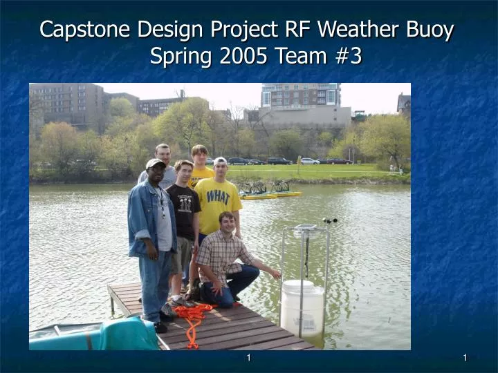
Capstone Design Project RF Weather Buoy Spring 2005 Team #3 1
Team #3: Expertise & Experience • Expertise: Power Distribution/Programming Experience: Cooper Power Systems • Expertise: Organizational skills, wiring hardware, Product Development Experience: Honeywell FM&T • Expertise: Computers / Law Experience: MPC Computers • Expertise: Computers and Communications Experience: JCI Internship • Expertise: Amplifier / Filter Design Experience: Academic • Expertise: Drives, Power Systems Controls Experience: P & H Mining Equipment • Nole Martin • Paul Simons • Eric Ritzke • Thomas Reuter • Steven Krol • Murtadha B. Tunis
1200 Man hours (Estimated) 2000+ Man hours (Actual) $1000 for material and prototyping (Estimated) $450 (Actual) Team #3: Total Resources
Wireless Weather Buoy Primary Benefit: Real-time Local Weather Information Intended for use by private water-front property owners. Product will report air and water temperature, barometric pressure and wind speed via RF communications. Similar weather stations exist, but not for private use. Maritime Consumer Market Selected Product
Similar Existing Product • Features • Wind speed • Wind direction • Barometer • Safety lights • GPS • Solar power • Humidity sensor • Water quality analyzer • Advantages of our product: • Cost effective • Only essential sensors • will be implemented
Basic Business Case • Estimated Average Product Selling Price: $700 • Estimated Product Annual Sales Volume: 1000 Units • Estimated Per Unit Cost of Parts and Materials: $300 • Estimated Per Unit Cost of Assembly, Testing and Mfg: $50 • Estimated Total Development Cost (Labor + Material): $494,000 • Calculated Annual Sales (ASP$ x Annual Volume): $700,000
Basic Business Case • Calculated Per Unit Cost Margin (ASP$ - [Parts + Materials + Mfg] x Costs$): $350 • Calculated Cost Margin (Per Unit CM$ / ASP$): 50% • Calculated Annual Cost Margin (CM% x Annual Sales$): $350,000 • Calculated Return On Investment (Est. Dev. Cost$ / Annual CM$): 1.411 Years.
Block Diagram Solar Recharging Battery Water & Air Temperature Sensor Pressure Sensor Wind Speed Sensor Power Conversion Circuits Microprocessor Microprocessor And Display 2 LED w/ Controls RF Transmitter RF Receiver Power Conversion Outdoor Unit (Buoy) Indoor Unit (Display) Eric – Green Paul - Yellow Murtadha – Orange Steve – Light Blue Nole – Red Tom – Dark Blue Data Lines Wireless Link Power Lines
Safety Standards • UL 458 - Power Converters/Inverters and Power Converter/Inverter Systems for Land Vehicles and Marine Crafts • UL 1196 - Standard for Safety for Floating Water Lights • 61010-1 - Electrical Equipment For Measurement, Control, and Laboratory Use • ISO 14000- Environmental Safety Standard • ISO 9001- Quality Insurance Standard
Display Power Paul Simons
Block Diagram Solar Recharging Battery Water & Air Temperature Sensor Pressure Sensor Wind Speed Sensor Power Conversion Circuits Microprocessor Microprocessor And Display Light Controller RF Transmitter RF Receiver Power Conversion Outdoor Unit (Buoy) Indoor Unit (Display) Data Lines Wireless Link Power Lines
To convert 120VAC to 5VDC To distribute power to the RF Receiver, the MPU, buffers and LED displays. Display Power Functional Purpose
Display PowerBlock Diagram 120VAC To 5VDC Wall Adapter Display Unit RF Receiver MPU Power Line Data Line
Display PowerDetailed Design Calculation Max Load Current vs. Max Tansformer Output Current Load Max Current Draw Receiver 15mA CPU 4mA LED Displays 240mA Total 259mA (<550mA)
Display Power Detailed Design DFM Analysis Plan The results of the analysis have shown the output ratings were within 5%, the output current was acceptable, and the ripple voltage was within spec.
Display PowerAssembly and Testing • Test to ensure 5V output and 550mA. • Solder leads from wall transformer to Toggle Switch found on PCB.
Display PowerVender Requirements To ensure buoy reliability and sustainability, the manufacturer of the wall transformer must: • Participate in ISO 9001 quality standards • Provide proof of EMC Standards are met • IEC/CISPR14-1 Household Appliances
Block #1: The Power Block Murtadha B Tunis 1
Block Diagram Solar Recharging Battery Water & Air Temperature Sensor Pressure Sensor Wind Speed Sensor 4 6 5 1 Power Conversion Circuits Microprocessor Microprocessor And Display 2 3 10 Light Controller RF Transmitter RF Receiver Power Conversion Circuits 7 9 8 11 Outdoor Unit (Buoy) Indoor Unit (Display) Data Lines Wireless Link Power Lines
Functional Purpose To receive Infra red rays from the sun to charge the solar panels To regulate the voltage for the charging circuit To recharge the available power for the battery To output the required regulated voltage for the power conversion circuit
Battery Life 15 years Battery Type 12V battery Rated Capacity < 84AH Supply voltage 12Vdc ± 3% Supply current <50mA Solar Panel <16.5V Performance Requirements
Block Interface Infra-Red Rays SUN Voltage Regulator Solar Panel Detail Design of Charging Circuit Voltage Regulator Power Conversion Circuit
Where R1 = 1.0K R2 = 1.2K
Voltage Regulator Calculation where Vref = 1.25V Iadj is typically 50uA
Worst case Max: Min:
Daily Energy Consumption Calculations Amps for battery From sensors/ Transmitter/CPU From sensors/ Transmitter/CPU Total Amp hour/day = 0.1006 A-hr/day
A rough rule of thumb gives battery capacity in terms of the number of days of storage required for different latitudes Latitude Days storage 0º - 30º 5-10 30º - 40º 10-15 40º - 50º 15-20 50º+ 20 + Battery Capacity calculation
The actual battery capacity required is the number of days storage multiplied by the daily load of the system Lat. Of Milwaukee is 42.950N 15 days * 0.1006A-hrs/day = 1.509 AH battery capacity. Battery capacity calculation
Wisconsin Solar Access Laws Authority 1:Wis. Stat. § 66.0401 Effective Date: 1/1/81 Authority 2:Wis. Stat. § 66.0403 Authority 3:Wis. Stat. § 236.292 Summary:Wisconsin law allows property owners with wind or solar-energy systems to apply for permits guaranteeing unobstructed access to solar and wind resources. A permit may not be granted if an obstruction already exists or if the construction of such an obstruction is well into the planning stages. In addition, a separate provision voids any restrictions on platted land that prevent or unduly restrict the construction and operation of solar-energy systems or wind-energy systems. Contact: Paul Helgeson Public Service Commission of Wisconsin 610 North Whitney Way P.O. Box 7854 Madison, WI 53707-7854 Phone: (608) 266-3905 Fax: (608) 266-3957
Summary Slides for Reliability • As shown, the solar panel and the 12V batteries would • fall at the buttom of the reliability chart, followed by the • comparator. This could be overcome by selecting for • wider voltage and current ratings.