Download
1 / 19
190 likes | 502 Views
UML & Prototyping. What is a prototype?. A prototype is a small-scale model. It can be (among other things): a series of screen sketches a storyboard, i.e. a cartoon-like series of scenes a Powerpoint slide show a video simulating the use of a system a lump of wood (e.g. PalmPilot)

E N D
What is a prototype? • A prototype is a small-scalemodel. It can be (among other things): • a series of screen sketches • a storyboard, i.e. a cartoon-like series of scenes • a Powerpoint slide show • a video simulating the use of a system • a lump of wood (e.g. PalmPilot) • a cardboard mock-up • a piece of software with limited functionality
Why prototype? • Facilitates evaluation and feedback • Stakeholders can see, hold, interact with a prototype more easily than with a document • Team members can communicate more effectively • You can test out ideas for yourself • Encourages reflection • Prototypes answer questions, and support designers in choosing between alternatives
What to prototype? • Work flow, task design • Screen layouts and information display • Difficult, controversial, critical areas • Prototypes Vs. Design
Compromises in prototyping • All prototypes involve compromises • For software-based prototyping maybe there is a slow response? Low-fidelity icons? limited functionality? • Two common types of compromise • ‘horizontal’: provide a wide range of functions, but with little detail • ‘vertical’: provide a lot of detail for only a few functions
Low-fidelity Prototyping • Uses a medium which is unlike the final medium, e.g. paper, cardboard • Intentionally rough and unfinished • Is quick, cheap and easily changed (?) • Encourages “high-level” criticism; problems with conceptual models and fundamental usability/functionality issues
High-fidelity prototyping • Prototype looks and behaves like (subset of) the final system • Commonly used tools: Macromedia Director, Visual Basic, and Smalltalk. • Users may think they have a full system (problem!) • Get at details of design (layout, icons, colors etc)
Prototype and Evaluation Early design Rough out on paper Low-fidelity (paper-based) Cognitive walkthrough Formative evaluation Action analysis Medium-fidelity Heuristic evaluation Functional prototype High-fidelity (computer-based) Empirical studies Late design
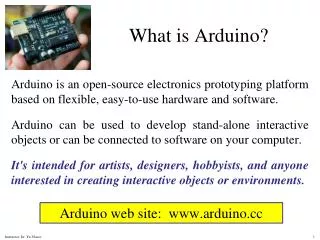
What is UML? • UML is a collection of OO design and specification techniques with a standardized notation • Modeling is key, modeling helps structure and analyze requirements • Functional model • Models system functionality (example: use case diagrams) • Object Model • Models structure of system (example: class diagrams) • Dynamic Model • Models internal behavior/interaction of system components (example: Sequence diagrams, state machine diagrams)
The purpose of UML diagrams • Models, and diagrams aimed at helping us think through problems, and document design decisions • UML offers a standardized set of diagrams, and a standardized set of notations, making communication more efficient • UML has a set of tools associated with it which help you: • Diagram (Visio, Dia) • Model transformation (ATL) • Code generation (BOUML, Codegen) • Reverse engineering (AgileJ, CodeLogic, Describe)
UML Diagrams In UML 2 there are 13types of diagrams: • Structure diagrams • Class diagram • Component diagram • Composite structure diagram • Deployment diagram • Object diagram • Package diagram • Behavior diagrams • Activity diagram • State machine diagram • Use case diagram • Interaction diagrams • Communication diagram • Interaction overview diagram • Sequence diagram • UML timing diagram http://www.agilemodeling.com/essays/umlDiagrams.htm
Use Case Diagrams Used to organize use-cases • Use cases. A use case describes a sequence of actions that provide something of measurable value to an actor and is drawn as a horizontal ellipse. • Actors. An actor is a person, organization, or external system that plays a role in one or more interactions with your system. Actors are drawn as stick figures. • Associations. Associations between actors and use cases are indicated in use case diagrams by solid lines. An association exists whenever an actor is involved with an interaction described by a use case. www.agilemodeling.com
Storyboards • Often used with scenarios, bringing more detail, and a chance to role play • It is a series of sketches showing how a user might progress through a task using the device
Activity diagram Flow charts modeling logic of a single use case www.agilemodeling.com
Class diagrams • A true classic – models domain & design • Shows classes, their relations, operations, and dependencies www.agilemodeling.com
Sequence diagrams • Aimed at modeling logic, or flow in your system; who interacts with what, and when • Different levels • Actors • Components • Objects • Time ↓ • Actors → www.agilemodeling.com
State Machine diagrams • Models possible states of objects as well as the flow/interaction of the system