Download
1 / 21
210 likes | 231 Views
Explore conditions for collision in WLANs near Bluetooth radios, studying frequency overlap, time overlap, interference energy, and network topology. Learn how these factors affect network performance.

E N D
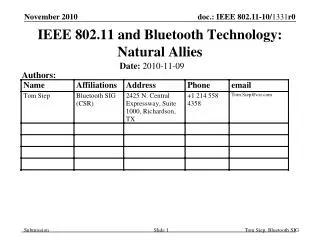
Reliability of IEEE 802.11 WLANs in Presence of Bluetooth Radios Jim Zyren jzyren@harris.com
Conditions for Collision • Frequency Overlap • Probability of collision is reduced by using a narrower occupied channel width • Time Overlap • Probability of collision is reduced by minimizing transmit time (ie transmit at higher data rate) • Sufficient Interference Energy • Interference energy can be reduced by: • spatial separation • tighter filtering • processing gain
t1 t0 t2 2.400 GHz 2.4835 GHz FHSS Networks are Frequency Agile FHSS and DSSS Power Spectral Densities 2.400 GHz 2.4835 GHz DSSS Networks typically use 3 fixed non-overlapping Channels
DSSS vs. Bluetooth • Early study of impact of Bluetooth on IEEE 802.11 DSSS system • IEEE 802.11 DSSS WLAN @ 11 Mbps • Dense environment of BT piconets • one DSSS WLAN node per 25 m2 of office space • BT piconet co-located with each DSSS node • 0 dBm BT tx power • +20 dBm DSSS tx power
40 m IEEE 802.11 AP IEEE 802.11 STA BT Piconet Enterprise Environment L.O.S. , range < 8m r3.3 , range > 8m Lpath = 20 log (4 p r / l ) r < 8m = 58.5 + 33 log( r/8 ) r > 8m where: l = wavelength @ 2.45 GHz (0.1224 m) r = range (m) Composite BT/DSSS Network Topology Simplified Propagation Model
4 m 20 m IEEE 802.11 AP IEEE 802.11 STA 10 m BT Piconet Impact of BT Interference Depends on Range from AP
BT Piconet User Model BT Single Piconet Utilization BT Composite Effects
625 m sec BT Transmission slots 259 m sec 1.94 dwell periods 1500 byte DSSS Hi Rate Packet (1210 msec) Interference Model
Thruput of DSSS WLAN vs. Piconet Load Effects shown are for a single BT Piconet operating in close proximity to IEEE 802.11 DSSS WLAN.
Availability Curve for DSSS WLAN (r = 4 m) For r = 4m, only one BT piconet is close enough to cause interference
Availability Curve for DSSS WLAN (r =10 m) At r = 10 m, 2 piconets are close enough to interfere with DSSS receiver
Availability Curve for DSSS WLAN (r = 20 m) At r = 20 m, 13 piconets are close enough to interfere with DSSS reception. IEEE 802.11 Hi Rate WLAN can still provide peak THROUGHPUT (7.2 Mbps) with 75% certainty, and 3.5 Mbps THROUGHPUT with over 99% certainty
Average Effect Over 8 Hour Day Average Effect over 8 hour working day is shown as a function of range from DSSS node to DSSS AP.
Summary of BT/DSSS Results • Degree of BT interference depends on: • local propagation conditions • density of BT piconets • BT piconet loading • DSSS susceptibility to BT interference increases as a function of range from DSSS node to DSSS AP • DSSS Hi Rate systems retain high throughput and have graceful degradation in the presence of BT interference • Based on these user models, DSSS Hi Rate WLANs are very reliable in the presence of significant BT interference • Results are preliminary. Must be verified by lab tests.
IEEE 802.11 FHSS vs. Bluetooth • Preliminary evaluation • interaction between single BT transmitter and an IEEE 802.11 FHSS link • 0 dBm BT Tx power, +20 dBm IEEE 802.11 tx power • Impact estimated under specific BT conditions: • Bluetooth idle (establish baseline IEEE 802.11 throughput) • BT telephony w/HV3 packet (33% BT piconet load) • BT file transfer w/DH1 packet (100% BT piconet load) • BT in PAGE mode (worst case) • Influence of Range and receiver filtering • IF filtering determines bandwidth of susceptibility to BT interference (about 3 MHz for IEEE 802.11 FHSS Rx)
Rx Desense Values (2FSK) (1) Vales stated in terms of interference-to-signal ratio (2) Interim values. To be finalized within 18 mos. after release
BT Tx Interference Range (D/2) Link Distance (D) 802.11 FH Node 802.11 FH AP Influence of Range (1 Mbps) Signal-to-Interference Ratio depends on: - relative BT and IEEE 802.11 Tx power - Range from IEEE 802.11 node to AP - Range from IEEE 802.11 node to BT Tx At 1 Mbps and 0 dBm BT Tx Power: - Bandwidth of interference susceptibility is 3 MHz - BT Tx must be approximately 50% closer to node than AP (0 dBm BT Tx power, +20 dBm IEEE 802.11FH Tx Power)
Throughput of WLAN Operating @ 1Mbps (2FSK) vs BT Load Note: Raw data rate for 2FSK = 1 Mbps
BT Tx Interference Range (D) Link Distance (D) 802.11 FH Node 802.11 FH Access Point Influence of Range (2 Mbps) At 2 Mbps and 0 dBm BT Tx Power: - Bandwidth of interference susceptibility is 3 MHz - BT Tx must be within roughly same distance to node as AP (0 dBm BT Tx power, +20 dBm IEEE 802.11FH Tx Power)
Throughput of WLAN Operating @ 2 Mbps (4FSK) vs BT Load Note: Raw data rate for 4FSK = 2 Mbps
Summary of FHSS/BT Results • Narrow channel width of FHSS systems help avoid interference in frequency domain • Occupied channel for FHSS is about 1 MHz under current FCC rules (same width for 2FSK and 4FSK) • Slower transmission rate requires longer transmit time • increases chances BT will hop into channel during transmission and collide (advantage for 4FSK) • Multi-level FSK more susceptible to ACI/CCI • 4FSK transmission can be jammed by a weaker BT signal (advantage 2FSK)