Download
1 / 27
270 likes | 485 Views
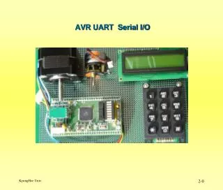
Serial I/O. Serial I/O. A generic protocol used to communicate between computers. Older than dirt – originally evolved from Morse Code The data is transmitted 1 bit at a time over a single wire Often using a UART - "Universal Asynchronous Receiver/Transmitter”

E N D
Serial I/O • A generic protocol used to communicate between computers. • Older than dirt – originally evolved from Morse Code • The data is transmitted 1 bit at a time over a single wire • Often using a UART - "Universal Asynchronous Receiver/Transmitter” • There is a protocol associated with the bus in order to convey information – RS-232 • When to start receiving (handshaking) • Data packet format • Speed • MPC 555 “SCI” unit implements a subset of this.
Serial I/O RS-232 basics: (as implemented in SCI) • When the bus is not in use, it stays HIGH* • a START bit initiates a transmission by going LOW* • data is sent LSB first (8 or 9 bits) • an optional PARITY bit is sent after the data for error checking • then a STOP bit is sent which goes HIGH* • if the bus remains HIGH* for > 1 character, the bus is considered IDLE *according to RS232: logic ‘1’ (“MARK”) is -3 to -15 V, logic ‘0’ (“SPACE”) is +3 to +15 V
Serial I/O • The Receiver (Rx) and Transmitter (Tx) don't share any clock • this is why it is called "asynchronous” • This is good because different computer systems can be connected • This is bad because it limits the speed the bus can run due to non-phase-locked time bases! • Without a common clock, the Tx and Rx must agree on a common bus speed (Baud rate) • Use the START bit to “synchronize” the start of transactions
Serial I/O • The Rx and Tx agree on a BAUD rate • The Rx then "over samples" the incoming data by (at least) 16x
Serial I/O • The Over-sample clock is derived from the BAUD rate clock • The Rx looks for a falling edge after an IDLE, this is the START bit • The Rx now counts its sample clock • It knows that the middle of the first data bit should be 24 clocks later • By spec, any frequency difference shouldn't cause a error or "slip" on an 8 or 9 bit transmission
Serial I/O • Serial Communications can be over a single wire • Uni-directional (called Simplex) • Bi-directional, not at the same time (Half-Duplex) • But most of the time its not: • Bi-directional at the same time (Full-Duplex)
Protocol Options • Baud Rate • RS-232 standard originally up to 19,200 bps • Most port UARTs fully support up to 115,200 bps • Data size • 8 bits (full ASCII) or 7 bits (low ASCII) • Parity • Used for error detection • Even parity – extra bit makes an even number of 1s • Odd parity – extra bit makes an odd number of 1s • Stop Bits – 1 or 2 • Flow control – prevent overflows
Other Serial Methods • There are multiple ways to transmit serial data (RS232 is just one) • 2-wire • Shared clock, data sampled on rising edge • Shared clock, data sampled on both edges • 1-wire • NRZ (Non-return-to-zero) • NRZI (Non-return-to-zero-inverted) • Used in USB (Universal Serial Bus)
NRZ • Non-return to zero (NRZ) - normal data transitions • The “Zero” refers to a dataless state in-between 1 and 0. • NRZ Inverted (NRZI, not a good description, is not inverse of NRZ). A transition for every zero bit. • Strings of zeros means lots of transitions. Strings of ‘1’s means steady line. NRZI
Bit Stuffing – a ‘0’ is inserted after every six consecutive ‘1’s in order to ensure a signal transition so that receiver clock can remain synchronized to the bit stream. Bit stuffing done automatically by sending logic. Sync pattern starts data transmission and is seven ‘0’s followed by a ‘1’.
USB • USB was the interface created to replace RS-232 serial • It’s still serial! • Much higher speeds: • “Super-speed” 3.2 Gbps • “High-speed” 480 Mbps • “full-speed” 12 Mbps • “legacy-speed” 1.5 Mbps • Mice and keyboards, for example • Speed comes from using a differential bus for the data signal • 2 wires for 1 bit
USB • Unlike RS-232 (for which data can come in at any time), USB is a polled bus. • All transactions are initiated by the Host, which means that USB devices do not use interrupts (at least as we know them).
QSMCM Module • Includes 3 modules • QSPI (Queued Serial Peripheral Interface) • Motorola/Freescale custom serial-type interface • Synchronous and full-duplex • 2x SCI (Serial Communication Interface) • Implements subset of RS-232 serial interface • Like the QADC, connects through the IMB3 bus interface
QSMCM Module • Global Registers: • QSMCMMCR - QSMCM Configuration Register • The usual – IMB Freeze, Stop, and SUPV • QSMCM Interrupt Level Registers: • QDSCI_IL • QSPI_IL • These registers set the IMB3 Interrupt Level (0-31) • Encoded numerically – not with the USIU encodings • In USIU, 0-6 would show up as level 0 through 6, levels 7-31 as level 7
QSMCM Module • Pin Control Registers: • Like the QADC, some of the QSPI pins can be converted to GPIO (General Purpose I/O) pins. • PQSPAR – PORTQS Pin Assignment Register • DDRQS – Data Direction Register • PORTQS – Data input/output port
SCI Interface • Setup steps: • Set the Baud Rate • Set the parity options • Data frame size (10 bits vs 11 bits) • Interrupt setup and enable • Transmit/Receive enable • Optional: Make the transmission “Queued”
Setting the Baud Rate SCCxR0 – SCI Control Reg 0 SCxBR controls Baud Rate (the others are reserved and should be 0) fsys / (32 * SCxBR) System clock for our board is 20 mhz
Setting up Options SCCxR1 – SCI Control Reg 1 Control Register 1 controls: • Parity options • Data packet size • Interrupt Enables • Transmit/Receive Enables
Making Transfers SCxDR — SCI Data Register All transfers (Transmit and Receive) occur through the data register Writing to the register transmits Reading from the register returns the last received packet
What’s the Status? SCxSR — SCIx Status Register RDRF and TDRE are keys to software • Allows for polling or interrupted handling of data • Would rather not sit and spin waiting for a byte to transmit
Queued Operation • Having to constantly feed the transmitter (or clear out the received data) causes a lot of interruptions in other operations. • In the grand scheme of “real-time” type systems, the serial connection is not often under a tight requirement • The SCI modules have built in 16-entry queues for taking some of the handling load away from the CPU
Queue Setup QSCI1CR – QSCI1 Control Reg QTE / QRE – Enables the queue for transmission / reception • Means RDRF and TDRE should beignored by software! Bits 4-7 control various interruption schemes
What’s the Status (of the Queue) ? QSCI1SR – QSCI1 Status Reg QTHF, QBHF, QTHE, QBHE are status bits that trigger the various interrupt conditions from the setup reg QRPNT – pointer to where we are in the queue QPEND – number of pending transmissions in the queue