Download
1 / 25
250 likes | 417 Views
ATLAS Forward Protons: Fast Time-of-Flight Detectors Michael Rijssenbeek – Stony Brook University for the ATLAS Forward Proton group. Quartic - the ATLAS Forward Proton Fast ToF Detector see also next talk: Diamond detectors by Gabriele Chiodini ( Universita del Salento ).

E N D
ATLAS Forward Protons:Fast Time-of-Flight DetectorsMichael Rijssenbeek – Stony Brook Universityfor the ATLAS Forward Proton group Quartic - the ATLAS Forward Proton Fast ToFDetector see also next talk: Diamond detectors by Gabriele Chiodini (Universita del Salento)
ATLAS Forward Timing Detectors Collaborating Institutions: Canada: U Alberta (CFD, HPTDC), U Toronto (Detector mounting); France: Saclay (SAMPIC RO chip) Germany: U Giessen (Radiators) Italy: Lecce, Roma2 (Diamond R&D) Portugal: Lisbon U (Trigger) USA: U Texas at Arlington (Detectors, MCP-PMT), Oklahoma State U (RO – Optoboards), U New Mexico (Irradiation), SLAC (Readout), Stony Brook U (Electronics, Readout, RPs) AFP Time-of-Flight Project Leader: Andrew Brandt (UTA) Many Thanks to all my colleagues for fruitful collaboration and help!
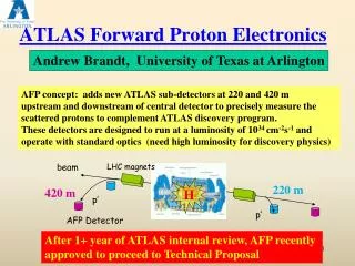
AFP – ATLAS Forward Protons AFP measurements: • Tag and measure momentum of intact protons from interactions seen in the central ATLAS detector • Soft QCD (Diffraction) in special low/medium-luminosity runs • avoid backgrounds from additional interactions in the same BX μ≃1 • cross sections are rather high: many pb’s • need clean interactions in ATLAS, i.e. low pile-up • need ~3 weeks-equivalent of data taking at μ≃1 (or ~1 week at μ≃3 ?) • at μ>1, require proton time-of-flight measurement to correlate forward protons with interaction vertex measured in central ATLAS detector σt=30 ps ⇔ σz=7 mm • Hard Central Diffraction in standard running (μ~50) • huge background from pile-up: 1 proton per side in each BX from soft QCD (Single Diffraction, etc.) • pile-up suppression requires precise proton time-of-flight measurement. • any increase spatial and temporal granularity improves efficiency and rejection AFP206 AFP214 AFP214 AFP206
Fast Time-of-Flight Main CEP background: overlap of SD protons with non-diffractive events = ‘pile-up’ background Reduce by: • central mass matching: • Mcentral = MAFP = (sξLeftξRight)½ • ToF: • zvtx = c(tLeft – tRight)/2 • E.g.: σt= 10 ps σzvtx= 2.1 mm • not a new idea; FP420: σt =20 ps: 0.1 σt =10 ps: 0.5 MX >800: 0.05
Diffractive Protons in AFP Number of protons per 100 fb–1 (~1 LHC yr) per Si pixel (50 μm × 250 μm): • Proton energy loss ξis related to x: • Central Mass M is related to both protons’ energylosses ξ1,ξ2 : ----- detector area (20 mm × 20 mm)
Hamburg Beam Pipe ATLAS design: Be floor and windows in Al structure • Tilted windows (11) minimize beam coupling and losses • Beryllium windows and floor, and Al structureminimize interactions and multiple scattering • Ample space for tracking and timing devices Results of detailed RF simulations: • Impedance Zlongis at the level of 0.5%/station at 1 mm from the beam • Similar for Ztrans • Power loss (heating) is manageable ~30 W, mostly in conical sections • Bellows are not yet included, but we are confident we can minimize their effect 450 mm ALUMINUM thin BERYLLIUM ALUMINUM - AUSTENITIC STEEL FLANGEs
AFP Roman Pot & Station AFP Pot adaptation from TOTEM design • shown with a possible timing detector … Copy RP Station design of ALFA & TOTEM: • Ample operational experience • Known cost and construction & installation procedures AFP Pot AFP timing beam TOTEM horizontal RP station(beam view)
Major Development Challenges • MCP-PMT Rate and Lifetime: • Have tube capable of 5 MHz and 5 C/cm2 (equivalent to 50 fb–1 !) • expect further 2-3× improvement • HPTDC board capable of 15 MHz • 5 ps resolution CFD • Clock Distribution Circuit <5 ps • All achieved !
proton AFP Fast Time-of-Flight QUARTIC concept: Mike Albrow for FP420 (joint ATLAS/ CMS effort) (2004) based on Nagoya Detector. • Initial design (~2006): 4 trains of 8 Q bars: 6mm × 6mm ×100mm • mounted at Cherenkov angle θČ ≃ 48° • Isochronous – Cherenkov light reaches tube at ~same time for each bar in a train • arrival time of proton is multiply measured: bar + readout resolution less stringent! • e.g 30 ps / bar 11 ps for train of 8 bars 2011 DOE Advanced Detector Research award for electronics development: θČ Č photons trains1 2 3 4 MCP-PMT HPTDC Board 8-Channel Preamplifier (PA-a) SMApigtails PA-b Programmable Gain Amp CFD Daughter Board Detector & PMT R&D: U Texas at Arlington (A. Brandt et al.); Electronics R&D: Stony Brook (M.R. et al)
Electronics Layout Phase 0 Baseline layout (8×8 channels/side): • if the CFD is sufficiently radiation-hard, it can be located at 214 m • if the HPTDC is sufficiently radiation-tolerant, it can be located at 214 m Feedthrough AFP2crate RR13 ?crate USA15crates Quartic Trigger (LMR600) CTF PA-b Trigger TDCToT LE 64× Signal (SMA) CFDToT Att PA-a Signals (50 Ω) Data OptoBoard BOC-RODor RCE LV+6V 5A LV+6V 20A DCS DCS DCS (μD) 8× Temp DCS DCS 2× Pressure iseg HV 8× HV (32 ch REDEL-HV) 214 m 214 m 240 m 0 m
Beam Test – FNAL 2012 (A.Brandt, UTA) 30 mm long Quartz bar // beam read bySiPM: σt≃ 10 ps for a SiPM (CFD only!) • excellent resolution! • not very radiation hard 2 mm wide × 6 mm deep (in beam direction) Quartz bar positioned at 48° with beam (Cherenkov angle),read by 10 μm pore MCP-MAPMT • single bar: σt≃ 20 ps (CFD only!) • 4 bars at 48° (~32 mm): expect ~10 ps • single bar with HPTDC: σt≃26ps • 6 bar train measurement (Test Beam): ~11 ps • rad hard tube (no degradation seen yet up to 5 C) Multiple measurements ‘tunable’ resolution, size, and interaction length … SiPM1 – SiPM3 SiPM3 – Qbar3
MCP-PMT Life Time (A.Brandt, UTA) • Historically MCP-PMT’s have not been extremely robust, their performance (QE) degrades from positive ion feedback • UTA Formed a collaboration with Arradiance and Photonis for coating … Arradiance 10 (25)m pore Planacon 20 ps single bar resolution at 5MHz proton rate (10 pe per proton) at 5E4 gain; x3-5 better with 10 m pore tube Hamamatsu ion barrier SL10 • Lehman et al. (Panda): As of 5/13 no loss in QE with Q>5 C/cm2! • >10× improvement over typical tube 1C~10 fb-1 • expect 3× more with next version 12
T958 DAQ FNAL 2012 Time difference between SiPM and average of 6 Q-bars: σt = 20 ps (SiPM: σt =14-15 ps) (A. Brandt, UTA) 2 3 4 5 6 7 Avg Using a 20-ch, 20 GHz, 40 GS/s (25ps/point) 500k$ LeCroy 9Zi scope! Thanks for the loan LeCroy !
Timing System Resolution Reached and extrapolated timing resolution: • Currently at 11-12 ps (Fall 2012 Test beam) with 6 bars; • ultimate performance of this system is probably about 8 ps
Time of Flight in Roman Pot • Bend the Quartic bars by 90° • disadvantage: loose light in the bend • advantage: extra degree of freedom inprojecting the bar onto the MA-PMT ! • Note: the Quartic concept is modular; • make ‘trains’ of ‘arbitrary’ length (limited by λint) choose σt • choose granularity: make trains of arbitrary width • beam test: 2 mm wide bar has same resolution as a 6 mm wide bar • optimize ToF detector’s size vs. σt vs. λint! • Possibility: make the light guide part of the bar into a mirrored air-guide! • reduce amount of material exposed to particles • reduce dispersion compared to quartz
Quartz vs. Air Light Guide … Simulations by Libor Nozka (Prague): • run 0: straight Q-bar 150 mm long • run 5: Bent Q-Bar 30/120 mm with mirror on elbow (R=90%) • run 6: Q-bar 30 mm + bent Air guide 120 mm with mirror on elbow (R=90%) (R = reflectivity of air guide) straight Q-bar 15 cm this design gives σt≃20 ps in beam test ns Q-bar 3 cm + bent airguide12 cm bent Q-bar 3+12 cm ns ns
Diffractive Protons in AFP Number of protons per 100 fb–1 (~1 LHC yr) per Si pixel (50 μm × 250 μm): • Proton energy loss ξis related to x: • Central Mass M is related to both protons’ energylosses ξ1,ξ2 : detector area (20 mm × 20 mm)
Efficiency & Backgrounds Royon, Sampert confirm pixellation of ~10 rows is adequate: • inefficiency per train: 7 trains: 2, 6×3.25 mm 10 trainsof 2 mm width 20 trainsof 1 mm width
New Nuclear Interaction Studies Concerns: • Scattering in first (upstream) station • this destroys proton which will neither be tracked nor timed global inefficiency • In case where this proton was kinematically disallowed it might create another proton inside the 2nd station’s acceptance • Scattering in the thin ‘floor’, spraying ‘sideways’ into the detector inside • At 14 TeV find about λInt≃2% per Q-bar (~8 mm of quartz) • 15% of events have an interaction by bar 8 • These interactions have a high multiplicity • Too many particles in quartz bar (shower) would saturate amps • dynamic range about 8-10 • O(10s) particles, which would saturate amps and cause that bar (and following) timing to be mismeasured • Time over Threshold functionality allows some recovery … All above influence the timing detector optimization Tom Sykora et al.
Severe Backgrounds at the LHC Sources: • IP: single diffraction pile-up • secondary interactions in upstream beam elements • Beam Halo Low-μ (special) runs: backgrounds are OK • see: ALFA runs at β* = 90 m, 1 km • OK for the soft diffraction program of AFP High-μ(standard) runs: backgrounds are very high • see: TOTEM standard-optics runs (Joachim Baechler’s talk) • evidence that the source is primarily IP and secondary interactions in collimators (1 & 2) • we are analyzing recently recovered ALFA run at β*=0.55 m (15’ run, 2 Mevts) • we are simulating the high-μ environment with β*=0.55 m optics … dominant !
from: Joachim Baechler’s talk of yesterday Horizontal RP Rate at 14 s Expected rates after LS1 are different(L, bunch scheme) Revolution frequency: 11.2 kHzaverage crossing rate : 11.2 * 1368 = 15.3 MHzaverage interaction rate (without separation) : 15.3 * 31= 47.4 MHz Beam conditions (fill # 3288): 1.6 x 10¹¹ p/b E = 4 TeV b* = 0.6 m en = 2.8 mm rad m = 31 (without separation)L = 6.7 x 1033 expected SD rate per arm within acceptance: ~ 0.4 / bx (event rate / bunch crossing) insertion at low β* beam heating – LHC vacuum – RP optimization- rates
Summary • AFP has a baseline fast timing detector • 10 ps or better resolution for 8 Q-bars • Long-lifetime MCP-PMT • Electronics • Optimization in progress: • Needs for μ≃1 physics • Backgrounds and efficiency … • Housing in a Roman Pot ? • Triggering
AFP – HBP plus Tracker … readout flex thin floor evaporativecooling sensors AFP AFP206 AFP214 AFP214 AFP206 ATLAS
AFP POT Modifications • AFP needs changes in the POT design: • the TOTEM design has a different thin window size, not optimally matched to our acceptance • the TOTEM floor is a groove in the pot bottom: • requires a bump-out of the tracking sensor, • making it difficult to insert a Quartic detector close to the beam … • We have more time than TOTEM use to investigate improvements • We should make the AFP pot a bit larger (to ~144 mm) by reducing the 2.5 mm gap between the bellows and the pot itself to ~1 mm. • Making it even larger than that requires a different ‘Tee’ design and RF calculations will have to be repeated to validate a larger cylinder. Unless absolutely necessary, I would prefer to keep the pot to 144 mm ID. • We should investigate alternative pot and window materials, coatings, etc. • e.g., a Be window of 200-400 μm thickness welded to an Al pot (cfr. Daniela) would be a huge improvement over the current TOTEM pot in terms of conductivity, radiation length (MS), and interaction length. • Need our own feedthrough plate with the services as we require them, adapting the plate as designed for TOTEM to AFP needs. • Possibly the plate for the ‘timing’ will be different from the plate for the ‘tracking’