Download
1 / 1
10 likes | 210 Views
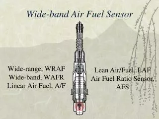
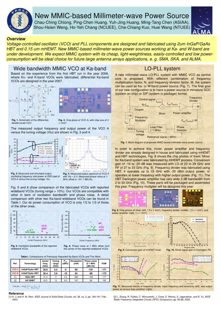
Frequency Divider. Control signal. f control. f osc -f control. N f osc. ÷ M. Coupler. Power amplifier. Mixer. N. Frequency Multiplier. (f osc -f control ) ÷M. f osc. Phase Detector. Loop Filter (~1 MHz). VCO. Tuning voltage. Reference signal (~MHz). Overview

E N D
Frequency Divider Control signal fcontrol fosc-fcontrol Nfosc ÷ M Coupler Power amplifier Mixer N Frequency Multiplier (fosc-fcontrol)÷M fosc Phase Detector Loop Filter (~1 MHz) VCO Tuning voltage Reference signal (~MHz) Overview Voltage-controlled oscillator (VCO) and PLL components are designed and fabricated using 2um InGaP/GaAs HBT and 0.15 um mHEMT. New MMIC-based millimeter-wave power sources working at Ka- and W-band are under development. We expect MMIC system with its cheap, light-weightiness, easily-controlled and low power-consumption will be ideal choice for future large antenna arrays applications, e. g. SMA, SKA, and ALMA. New MMIC-based Millimeter-wave Power Source Chau-Ching Chiong, Ping-Chen Huang, Yuh-Jing Huang, Ming-Tang Chen (ASIAA), Shou-Hsien Weng, Ho-Yeh Chang (NCUEE), Che-Chiang Kuo, Huei Wang (NTUEE) LO-PLL system Based on the experience from the first HBT run in the year 2006, where Ku- and K-band VCOs were fabricated, differential Ka-band VCOs are designed in the year 2007. A new millimeter-wave LO-PLL system with MMIC VCO as central core is proposed. With different combination of frequency multiplication factor, N, and frequency division factor, M, the system can be used as Ka- or W-band power source (Fig. 7). The final goal of our new configuration is to have a power source in miniature SOC (system on chip) or SIP (system in package) format. Fig. 1.Schematic of the differential, double-tuned VCO. Fig. 2. Chip photo of VCO A, with chip size of 2 x 1mm2. The measured output frequency and output power of the VCO A versus the tuning voltage (Vtu) are shown in Fig. 3 and 4. Fig. 7. Block diagram of proposed MMIC-based millimeter-wave power source. In order to achieve this, mixer, power amplifier and frequency divider are already designed in house and fabricated using mHEMT and HBT technologies. Fig. 8 shows the chip photos of them. Mixer for Ka-band system was fabricated by mHEMT process. Conversion gain of -10 to -20 dB was measured with LO of 23 to 29 GHz and RF of 27 to 33 GHz (Fig. 9). Frequency divider was fabricated using HBT. It operates up to 15 GHz with -20 dBm output power, or operates at lower frequency with higher output power (Fig. 11). The HBT Darlington power amplifier has very wide 3 dB bandwidth from 2 to 30 GHz (Fig. 10). These parts will be packaged and assembled this year. Frequency multiplier will be designed this year. Wide bandwidth MMIC VCO at Ka-band Fig. 3.Measured and simulated output oscillating frequency and power at GSG pad of VCO A versus the tuning voltage,Vtu. Fig. 4.Measured output spectrum of VCO A with Vtu = 0 V. Measured phase noise at 1-MHz offset is -101.7 dBc/Hz. Fig. 5 and 6 show comparison of the fabricated VCOs with reported wideband VCOs (tuning range > 10%). Our VCOs are compatible with other in term of oscillation bandwidth and phase noise. A detail comparison with other two Ka-band wideband VCOs can be found in Table I. Our dc power consumption of VCO is only 1/2 to 1/3 of those of the other ones. Fig. 8. Chip photos of mixer (left, 1.5 x 1 mm2), frequency divider (middle, 1.5 x 1 mm2), and power amplifier (right, 1 x 1 mm2). VCO 2007 VCO 2007 VCO 2006 VCO 2006 Fig. 5. Oscillation bandwidth of the reported wideband VCOs. Fig. 6. Phase noise at 1 MHz offset from the carrier of the reported wideband VCOs. Fig. 9. Conversion gain of mHEMT mixer. Fig. 10. Small signal gain of Darlington PA. Table I. Comparisons of Previously Reported Ka-Band VCOs and This Work. Fig. 11. Measured results of frequency divider. Input frequency and sensitivity (left), and output power at various bias condition (right). Reference [1] H. Li and H. M. Rein, IEEE Journal of Solid-State Circuits, vol. 38, no. 2, pp. 184-191, Feb. 2003. [2] L. Zhang, R. Pullela, C. Winczewski, J. Chow, D. Mensa, S. Jaganathan, and R. Yu, IEEE Radio Frequency Integrated Circuits (RFIC) Symposium, pp. 85-88, 2002.