Download
1 / 13
180 likes | 803 Views
Karnaugh Maps (K maps). What are Karnaugh 1 maps?. Karnaugh maps provide an alternative way of simplifying logic circuits . Instead of using Boolean algebra simplification techniques, you can transfer logic values from a Boolean statement or a truth table into a Karnaugh map .

E N D
What are Karnaugh1 maps? • Karnaughmaps provide an alternative way of simplifying logic circuits. • Instead of using Boolean algebra simplification techniques, you can transfer logic values from a Boolean statement or a truth table into a Karnaugh map. • The arrangement of 0's and 1's within the map helps you to visualise the logic relationships between the variables and leads directly to a simplified Boolean statement. 1Named for the American electrical engineer Maurice Karnaugh.
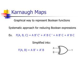
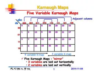
Karnaugh maps • Karnaugh maps, or K-maps, are often used to simplify logic problems with 2, 3 or 4 variables. Cell = 2n ,where n is a number of variables For the case of 2 variables, we form a map consisting of 22=4 cells as shown in Figure A A A 0 1 0 1 0 1 B B B 0 0 0 0 2 1 1 1 1 3 Maxterm Minterm
Karnaugh maps • 3 variables Karnaugh map Cell = 23=8 AB C 00 01 11 10 0 6 4 2 0 3 7 1 5 1
Karnaugh maps • 4 variables Karnaugh map AB 00 01 11 10 CD 0 4 12 8 00 1 13 5 9 01 3 7 15 11 11 6 2 10 14 10
Karnaugh maps • The Karnaugh map is completed by entering a '1‘(or ‘0’) in each of the appropriate cells. • Within the map, adjacent cells containing 1's (or 0’s) are grouped together in twos, fours, or eights.
Example 2-variable Karnaugh maps are trivial but can be used to introduce the methods you need to learn. The map for a 2-input OR gate looks like this: A 0 1 B 1 0 A 1 1 1 B A+B
Example AB 01 C 00 11 10 1 1 0 1 1 1 1
Exercise • Let us use Karnaugh map to simplify the follow function. F1 = m0+m2+m3+m4+m5+m6+m7 F2 =m0+m1+m2+m5+m7 • Answer
Exercise Given the truth table, find the simplified SOP and POS form.
Exercise • Design two-level NAND-gate logic circuit from the follow timing diagram.
Don’t care term AB 00 01 11 10 CD 00 01 11 10 AD
Exercise • Design logic circuit that convert a 4-bits binary code to Excess-3 code