Download
1 / 31
310 likes | 470 Views
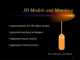
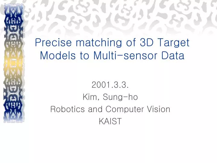
Precise matching of 3D Target Models to Multi-sensor Data. 2001.3.3. Kim, Sung-ho Robotics and Computer Vision KAIST. Contents. Introduction Overall Structure Target Detection Hypothesis Generation Multi-sensor 3D Target Matching Target Model Feature Prediction

E N D
Precise matching of 3D Target Models to Multi-sensor Data 2001.3.3. Kim, Sung-ho Robotics and Computer Vision KAIST
Contents • Introduction • Overall Structure • Target Detection • Hypothesis Generation • Multi-sensor 3D Target Matching • Target Model Feature Prediction • Model-driven Image Feature prediction • Local Search to Achieve Coregistration • Error terms • Results • Conclusion Robotics&Computer Vision
Introduction • Recognition • We cannot recognize what we do not know • Object descriptions, or models, are already available -> model-based recognition • Basic operation • Identification: determine the nature of the object imaged • Location: determine the position in 3D space of the object Robotics&Computer Vision
Introduction • Goal • Target recognition using multi-sensor fusion (optical:CCD+FLIR, LADAR) • Coregistration=pose refinement + registration • Pose: target model+sensor suite • Registration: intersensor alignment Robotics&Computer Vision
Overall Structure • System components • Optical sensor: color image sensor, FLIR sensor • Range sensor: LADAR(Laser raDAR) • Solaris workstation Robotics&Computer Vision
Overall Structure • Basic assumptions • 3D target models are given • 3 sensors are fixed to a solid platform • 3 sensors are nearly boresight align • Ground looking: sensors on the ground plane looking out across terrain Robotics&Computer Vision
Overall Structure Robotics&Computer Vision
Target detection • Goal: classify either target or background • Feature: target color • Training imagery covers • Time, lighting condition, target type -> generate LUT • Algorithm • Multivariate decision trees ->geneate ROI Robotics&Computer Vision
Hypothesis Generation • Goal: generate hypothesis for target type, position, orientation • Method: using template matching • Compare CAD model with range data • Scoring measure: high scores are better Robotics&Computer Vision
Multisensor 3D Target Matching • Procedure • Target Model Feature Prediction • Model-driven Image Feature prediction • Local Search to Achieve Coregistration • Error function Robotics&Computer Vision
Target Model Feature Prediction • CAD model (ex.BRL-CAD) • Highly detailed CSG(constructive solid model) • Difficult for matching to sensor data directly • Need to extract feature • 3D silhouette feature: suitable for matching optical imagery • Sampled surface: suitable for matching range imagery Robotics&Computer Vision
Target Model Feature Prediction • Silhouette lines • Assign a unique color to each face • Rendering from the hypothesized viewing angle -> orthographic projection • Choose pixels adjacent to the unique background color -> the target silhouette • Internal lines(not necessary in FLIR) • Obtain the direction of the sun -> used to predict the internal model edges • Dot product: sun, faces -> same sign rejected Robotics&Computer Vision
Target Model Feature Prediction • Model edges predicted for matching to the optical Images Robotics&Computer Vision
Target Model Feature Prediction • Sampled surface • Used for range matching • CAD model->range sensor’s coordinate • Sampled surface obtained through ray intersection Robotics&Computer Vision
Model-driven Image Feature Extraction • Conventional: bottom-up line extraction • Unreliable in real image • Need to use model-driven approach • Model-driven approach: top-down • Search is initiated at the locally best corresponding line segment • Place a silhouette edge to maximize tuned gradient response(when matching) Robotics&Computer Vision
Model-driven Image Feature Extraction • Oriented gradient mask:G(a,b) • Response to gradient mask: (a, b): current mask position (i, j): mask position being calculated : rotation required j b a i Robotics&Computer Vision
Local Search to Achieve Coregistration • Develop • Error function • Model feature to data • Search mechanism • Finding pose estimate minimizing error • Match error function c: particular correspondence mapping b.w. model & sensor feature C: correspondence space F: coregistration of the sensors relative to the model Robotics&Computer Vision
Local Search to Achieve Coregistration • About c(correspondence) • Pairing b.w. sampled surface and range point • Pairing b.w. line segment and optical imagery • About F(coregistration) • Geometric relationship b.w. the sensors and the model • 8 dim. Vector • 3+3: Target pose relative to the optical sensor • 2: Planar translation optical image plane to range sensor’s image plane Robotics&Computer Vision
Local Search to Achieve Coregistration • Matching strategy • Correspondence-space search(c -> F) • First, find c* minimizing error function • Second, find optimal F given c* • Ineffective when correspondence space large • Coregistration-space search(F -> c) • First, estimate F • Second, find c* given F • Effective: fixed size F(8 dim.) Robotics&Computer Vision
Local Search to Achieve Coregistration • Coregistration-space search • Error • Optical feature error: function of gradient response to a tuned filter for line segment • Range error: function of Euclidean dist. from sampled surface to range data Robotics&Computer Vision
Local Search to Achieve Coregistration • Coregistration-space search: generate & test • Local search samples each in F about current estimate • Feature prediction using hypothesis F • The move with lowest error is taken • Repeat until local optima are reached • If F is changed, the pose considered Robotics&Computer Vision
Error Terms • Overall error terms • Each=omission error+fitness error ,s->o,r • Omission error=color + IR weights Robotics&Computer Vision
Error Terms • Optical fitness error: • Represents how well each model line fits the underlying image • Erorr term: Robotics&Computer Vision
Error Terms • Range fitness error: • Represent how well the sampled surface model points fit the actual range data • Euclidean distance b.w.model point and data point • Nearest neighbor: • Fitness error: • Total fitness error: Robotics&Computer Vision
Error Terms • Omission Error: • Accounts for weak response in optical and unmatched points in range • Optical omission error • Range omission error Robotics&Computer Vision
Results • Error terms Robotics&Computer Vision
Results Robotics&Computer Vision
Results Robotics&Computer Vision
Result(from web) Robotics&Computer Vision
Conclusion • It demonstrated the ability to find geometrically precise matches b.w. CAD models and multi-sensor data. • The algorithm is able to reduce errors and generate improved matches. • It is future work to match from 3D Model to multi - sensor image in all conditions like day, night . Robotics&Computer Vision
References • Mark R. Stevens, J. Ross Beveridge, Precise Matching of 3-D Target Models to Multisensor Data,CSU, Jan. 20, 1997. • J. Ross Beveridge,el al., RossProgress on Target and Terrain Recognition Research at Colorado State University,CSU,Dec.16,1995. • Mark R. Stevens, J. Ross Beveridge, Optical Linear Feature Detection Based on Model Pose, CSU, Dec.16, 1995. • Mark R. Stevens, J. Ross Beveridge, Interleaving 3D Model Feature Prediction and Matching to Support Multi-Sensor Object Recognition, CSU, Dec.16, 1995. Robotics&Computer Vision