Download
1 / 17
170 likes | 335 Views
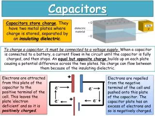
Capacitors. Capacitance is the ability of a component to store energy in the form of an electrostatic charge. A Capacitor is a component designed to provide a specific measure of capacitance. Capacitor Construction. Parallel plates separated by a dielectric layer. Fixed Value Capacitors

E N D
Capacitors Capacitance is the ability of a component to store energy in the form of an electrostatic charge. A Capacitor is a component designed to provide a specific measure of capacitance. EGR 101
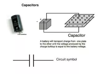
Capacitor Construction Parallel plates separated by a dielectric layer EGR 101
Fixed Value Capacitors • Polarized Electrolytic Capacitors • Most electrolytic capacitors are polarized EGR 101
Variable Capacitors Interleaved-Plate Capacitors EGR 101
Charging a Capacitor • Electrostatic Charge Develops on the Plates • Electrostatic Field Stores energy EGR 101
Discharging a Capacitor Apply a discharging component (here a short circuit) across the capacitor. (Safer to use a resistor!) EGR 101
Capacity (Capacitance) of a Device Capacity is the amount of charge that a capacitor can store per unit volt applied. Capacity is directly proportional to charge and inversely proportional to voltage EGR 101
where C = the capacity (or capacitance) of the component, in coulombs per volt, or Farads Q= the total charge stored by the component V= the voltage across the capacitor EGR 101
Example EGR 101
Capacitor Ratings • Most capacitors rated in the picofarad (pF) to microfarad (F) range • Capacitors in the millifarad range are commonly rated in thousands of microfarads: 68 mF = 68,000 F • Capacitors in the nanofarad range are also commonly rated in microfarads: • 68 nF = 0.068 F EGR 101
Capacitors in the nanofarad range are also commonly rated in microfarads: • 68 nF = 0.068 F • Tolerance • Usually fairly poor • Variable capacitors used where exact values required EGR 101
Capacitor Value Codes • Physically large capacitors usually have their values printed directly on the case • Smaller capacitors are generally labeled using a code: • 2-digit code: the number represents the value of the component in pF Example: 15 = 15 pF • 3-digit code: the code is interpreted like the first three digits of a resistor code Example: 473 = 47 x 103pF = 47 nF • The numbers 6 and 7 are not used as multiplier values • The numbers 8 and 9 are decoded as follows: 8 = 0.01 and 9 = 0.1 Example: 158 = 0.15 pF
C = the capacity of the component, in farads (8.85 X 10⁻¹²)= the permittivity of a vacuum, in farads per meter (F/m) r= the relative permittivity of the dielectric A= the area of either plate, in square meters (m2) d = the distance between the plates, in meters (m) EGR 101
Plate Area: capacitance is directly proportional to plate area • Dielectric Thickness: capacitance is inversely proportional to dielectric thickness • Dielectric Permittivity: the ease with which lines of electrical force are established in the dielectric material • Relative Permittivity: the ratio of a material’s permittivity to that of a vacuum EGR 101
Capacitors in Series CT = the total series capacitance Cn = the highest-numbered capacitor in the circuit EGR 101
Capacitors in Parallel Cn = the highest-numbered capacitor in the parallel circuit EGR 101