Download
1 / 18
200 likes | 312 Views
Explore the block diagram, functional tables, timing diagrams, and ASM charts of SRAM controllers in FPGA and ASIC design. Learn about SRAM timing parameters and the role of memory controllers.

E N D
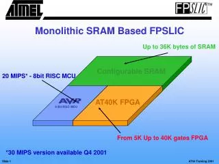
Lecture 15External SRAM ECE 448 – FPGA and ASIC Design with VHDL
Required reading • P. Chu, FPGA Prototyping by VHDL Examples • Chapter 10, External SRAM ECE 448 – FPGA and ASIC Design with VHDL
Block diagram of a typical SRAM ECE 448 – FPGA and ASIC Design with VHDL
SRAM Functional Table ECE 448 – FPGA and ASIC Design with VHDL
SRAM Simplified Functional Table ECE 448 – FPGA and ASIC Design with VHDL
Timing diagram of an address-controlled read cycle ECE 448 – FPGA and ASIC Design with VHDL
Timing diagram of an output_enable-controlled read cycle ECE 448 – FPGA and ASIC Design with VHDL
SRAM Timing Parameters (in ns) ECE 448 – FPGA and ASIC Design with VHDL
Timing diagram of write cycle ECE 448 – FPGA and ASIC Design with VHDL
SRAM Timing Parameters (in ns) ECE 448 – FPGA and ASIC Design with VHDL
Role of a memory controller ECE 448 – FPGA and ASIC Design with VHDL
Block diagram of a memory controller ECE 448 – FPGA and ASIC Design with VHDL
ASM chart of a safe SRAM controller ECE 448 – FPGA and ASIC Design with VHDL
ASM chart of a testing circuit ECE 448 – FPGA and ASIC Design with VHDL
ASM chart of an alternativeSRAM controller: design I ECE 448 – FPGA and ASIC Design with VHDL
ASM chart of an alternativeSRAM controller: design II ECE 448 – FPGA and ASIC Design with VHDL
ASM chart of an alternativeSRAM controller: design III ECE 448 – FPGA and ASIC Design with VHDL
Generating a half cycle with DDR ECE 448 – FPGA and ASIC Design with VHDL