Download
1 / 27
270 likes | 300 Views
This tool bridges the gap between CAD and GEANT environments by converting CAD files to GEANT for simulation, with support for various output formats. It aids in translating complex detector designs for streamlined simulation.

E N D
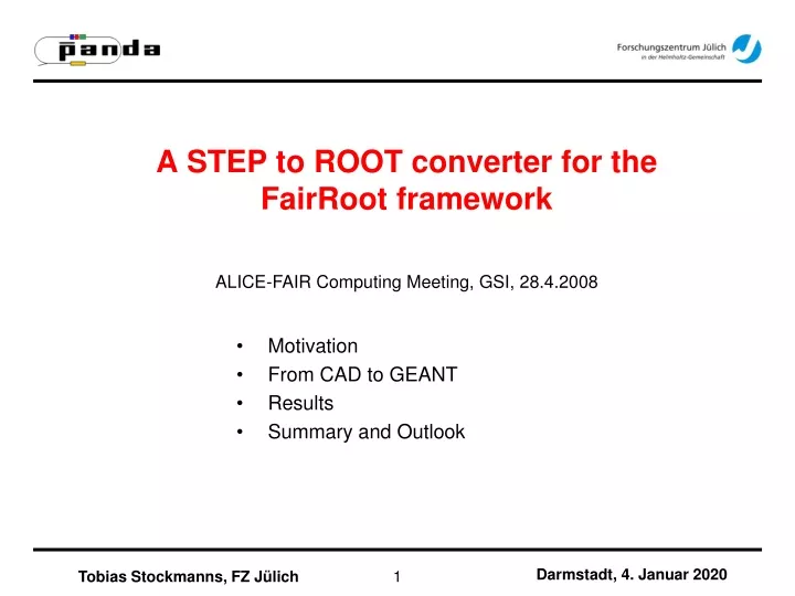
A STEP to ROOT converter for theFairRoot framework ALICE-FAIR Computing Meeting, GSI, 28.4.2008 Motivation From CAD to GEANT Results Summary and Outlook Tobias Stockmanns, FZ Jülich
Motivation • The design of a complex detector is usually done in CAD programs by engineers in a Windows environment while the simulation of the geometry is performed by physicists in a linux environment with GEANT as particle propagation tool • The way both handle geometries is fundamentally different and there is no (as far as I know) working converter between both environments • This implies that the design of the geometry of a detector has to be done twice, often from different people with all kind of problems connected with this • For me the first and most important (and most complicated) step was to write a program which would help me to translate a CAD file into a geometry for simulation. • As an input file format STEP was chosen because it is the de facto standard for the exchange of CAD files between different CAD programs Darmstadt, 4. Januar 2020 Tobias Stockmanns, FZ Jülich
General structure CAD GEANT Top assembly World volume Assembly Logical volume Part Solid Darmstadt, 4. Januar 2020 Tobias Stockmanns, FZ Jülich
Example: Module active Sensor Pixel module dead copper Flex MCC capton Front-ends FE Darmstadt, 4. Januar 2020 Tobias Stockmanns, FZ Jülich
CAD Parts Geant Solids Geant CAD Solids are represented by their boundaries (BREPS) The object itself does not know what type of geometrical body it is. For example:a box is described as an object consisting of six surfaces which are planes. Each plane consists of four edges which are lines and each line has a start and stop vector. Bodies are created by basic solids like torus, box, cylinder, sphere and a few more. More complex solids can be created by boolean combination of basic objects Find Geant object which fits to the bunch of surfaces of the CAD program and extract the parameters Darmstadt, 4. Januar 2020 Tobias Stockmanns, FZ Jülich
CAD Parts Geant Solids Geant CAD With the creation of the solid the origin and the orientation are given For example:With the creation of a tube the origin is in the center of the tube and the z-axis is parallel to the symmetry axis of the tube The origin and the orientation of the solid within its local coordinate system is not defined by construction For example: Calculate the transformation matrix which transforms the CAD coordinate system into the Geant coordinate system. • The origin of the box is not in the center • No edge is parallel to the axes of the coordinate system Darmstadt, 4. Januar 2020 Tobias Stockmanns, FZ Jülich
Program structure Transformation from OpenCascade objects to GEANT objects Done by OpenCascade Converts files into OpenCascade Objects STEP file does not contain material information external file with name of solid and material replacement file covered later Darmstadt, 4. Januar 2020 Tobias Stockmanns, FZ Jülich
Conversion OpenCascade Geant BREPS Geant solids Darmstadt, 4. Januar 2020 Tobias Stockmanns, FZ Jülich
Program structure Recursive construction of Geant like volumes Analyzes the BREPS to find the matching Geant solid Darmstadt, 4. Januar 2020 Tobias Stockmanns, FZ Jülich
Program structure Extracts the parameters of the solid and calculates the transformation matrix Darmstadt, 4. Januar 2020 Tobias Stockmanns, FZ Jülich
Program structure Output of the data into a root file Other output formats possible Darmstadt, 4. Januar 2020 Tobias Stockmanns, FZ Jülich
What is the status? DDL output CBM output Root output supports now: box tube cone trap subtraction-solid Arb8 Xtru Darmstadt, 4. Januar 2020 Tobias Stockmanns, FZ Jülich
MVD-Geometry Darmstadt, 4. Januar 2020 Tobias Stockmanns, FZ Jülich
MVD Geometry in ROOT Darmstadt, 4. Januar 2020 Tobias Stockmanns, FZ Jülich
Output files • Three output files: • Root_Output.root:the root file with the geometry (with or without geometry manager) • Unknown_Parts.dat:list of solids which could not be recognized by the analyze part class • Missing_Materials.datlist of solids were no material information was provided. This parts are nevertheless created inside root could cause problems in particle tracking Darmstadt, 4. Januar 2020 Tobias Stockmanns, FZ Jülich
Solenoid Solenoid much more complex. Many special geometries without corresponding root geometries Darmstadt, 4. Januar 2020 Tobias Stockmanns, FZ Jülich
Solenoid Darmstadt, 4. Januar 2020 Tobias Stockmanns, FZ Jülich
Extension of CadConverter • Some geometries are too complex for an automatic conversion • Others are too complex for fast tracking in simulation • Possibility implemented to replace any assembly within the tree of a geometry by a new one Darmstadt, 4. Januar 2020 Tobias Stockmanns, FZ Jülich
Replacement File • Instructions for the replacement of assemblies within the main STEP file are given in an additional ASCII file • General structure of the file: • Name of the assembly which should be replaced • The method used to create the new assembly (see later) • The necessary informations • A line „EndPartDescription“ • Three methods supported: • „StringPart“ • „StepPart“ • „RootBooleanPart“ Darmstadt, 4. Januar 2020 Tobias Stockmanns, FZ Jülich
String Part PixelDisk StringPart BOX x 10 y 20 z 12 EndPartValues 1 0 0 0 0 1 0 1 0 0 1 0 EndPartDescription Name of the original assembly Method Part name parameters (any order) transformation matrix Darmstadt, 4. Januar 2020 Tobias Stockmanns, FZ Jülich
StepPart Name of the original assembly PixelDisk2 StepPart /home/stockman/OpenCascade/OpenCascade6.2/samples/standard/ts/dat/Module_8FE.stp EndPartDescription Method Path to STEP file Darmstadt, 4. Januar 2020 Tobias Stockmanns, FZ Jülich
RootBooleanPart Name of the original assembly PixelDiskMixed RootBooleanPart /home/stockman/OpenCascade/OpenCascade6.2/samples/standard/ts/dat/BoxInSpace.stp /home/stockman/OpenCascade/OpenCascade6.2/samples/standard/ts/dat/PixelDiskRing.stp EndFileList PixelDiskRing – BoxInSpace EndPartDescription Method • Path to STEP files • (as many as necessary) File list ended by „EndFileList“ • Operation (+,-,/,(,)) • Transformation matrizies are added • automatically • Supports assemblies Darmstadt, 4. Januar 2020 Tobias Stockmanns, FZ Jülich
Barrel Yoke Darmstadt, 4. Januar 2020 Tobias Stockmanns, FZ Jülich
RootBooleanPart - BarrelYoke710NewoAdd - BarrelYoke710NewoSub (BarrelYoke710NewoEndPlate:BarrelYoke710NewoEndPlateoTrans1+BarrelYoke710NewoRing1:BarrelYoke710NewoRing1oTrans1+BarrelYoke710NewoRing2:BarrelYoke710NewoRing2oTrans1+BarrelYoke710NewoRing3:BarrelYoke710NewoRing3oTrans1+BarrelYoke710NewoRing4:BarrelYoke710NewoRing4oTrans1+BarrelYoke710NewoRing5:BarrelYoke710NewoRing5oTrans1+BarrelYoke710NewoRing6:BarrelYoke710NewoRing6oTrans1+BarrelYoke710NewoRing7:BarrelYoke710NewoRing7oTrans1+BarrelYoke710NewoRing8:BarrelYoke710NewoRing8oTrans1+BarrelYoke710NewoRing9:BarrelYoke710NewoRing9oTrans1+BarrelYoke710NewoRing10:BarrelYoke710NewoRing10oTrans1) -(BarrelYoke710NewoHoleBack:BarrelYoke710NewoHoleBackoTrans1+BarrelYoke710NewoHoleBack:BarrelYoke710NewoHoleBackoTrans2+BarrelYoke710NewoHoleBack:BarrelYoke710NewoHoleBackoTrans3+BarrelYoke710NewoHoleBack:BarrelYoke710NewoHoleBackoTrans4+BarrelYoke710NewoHoleFront:BarrelYoke710NewoHoleFrontoTrans1+BarrelYoke710NewoHoleFront:BarrelYoke710NewoHoleFrontoTrans2+BarrelYoke710NewoHoleFront:BarrelYoke710NewoHoleFrontoTrans3+BarrelYoke710NewoHoleFront:BarrelYoke710NewoHoleFrontoTrans4+BarrelYoke710NewoCryoHole:BarrelYoke710NewoCryoHoleoTrans1+BarrelYoke710oTarget:BarrelYoke710oTargetoTrans1+BarrelYoke710oTarget:BarrelYoke710oTargetoTrans2+BarrelYoke710NewoTrap:BarrelYoke710NewoTrapoTrans1) Darmstadt, 4. Januar 2020 Tobias Stockmanns, FZ Jülich
Root Drawings Darmstadt, 4. Januar 2020 Tobias Stockmanns, FZ Jülich
Summary • CAD converter is able to convert STEP files into “GEANT like” geometries • Works best for ROOT geometries because ROOT is able to have assemblies without a predefined bounding box (or volume) • It Is in use for the PANDA Micro-Vertex-Detector and the PANDA solenoid magnet within the PandaRoot framework • Remarks: • It only works for simple geometries • For more complex ones a replacement mechanism exists • It has some problems with CATIA STEP files Solution: load them into Autodesk Inventor run a small macro and save them as new STEP files Darmstadt, 4. Januar 2020 Tobias Stockmanns, FZ Jülich
Outlook • Add support for: • more boolean objects (add the moment only a subtraction of a volume in a plane is supported) • cables and tubes • handling of B-splines • loading of the media information Darmstadt, 4. Januar 2020 Tobias Stockmanns, FZ Jülich