Download
1 / 23
230 likes | 282 Views
Learn why Assembly Language is vital, explore CPU design, registers, and instruction set with a focus on data transfer and manipulation. Includes pointers and examples.

E N D
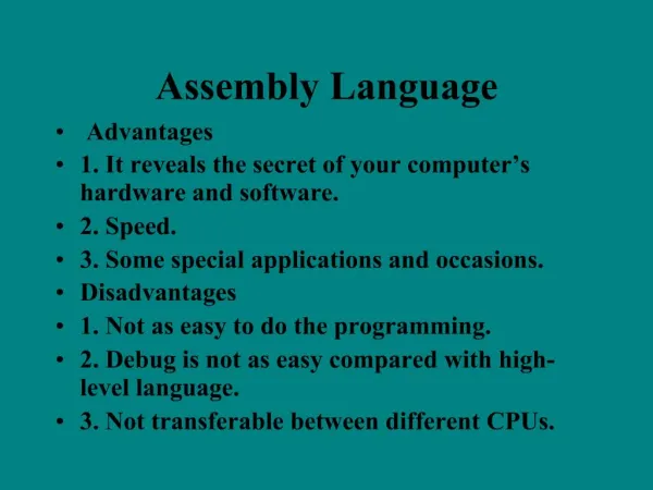
Assembly Language CS 6303 Rashad Sierra
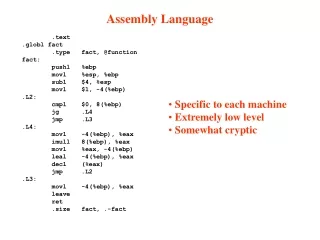
What is Assembly Language and why do we need it? • The CPU only understands machine language. • Machine language is “a binary language, which means that all machine language instructions are in binary form” (Runnion pg2) • “Assembly Language is just a symbolic form of machine language.” (Runnion pg2) • In order to run on the CPU, every program must be converted into machine language. • In essence we are programming within the CPU.
The CPU Design Graphic taken from Art of Assembly by Randall Hyde
Assembler • The Assembler performs the translation from assembly language to machine language. • It is essentially a compiler that lets you address and access memory directly. • It has a defined Instruction set consisting of opcodes and operands. • It gives you access to the processor registers set.
The Registers Set • “The Register set consist of all registers in the CPU that are accessible to the programmer.” (Mano & Kime, pg 484) • A register is the fastest of all temporary storage type because it is a logical circuit that only depends on the clock and input • All the registers are 16 bits long in Intel 8088 processor. • There are eight general-purpose registers, four Segment Registers, and two Control Registers available to the programmer.
General Purpose Registers • The General Registers have three categories • Data Registers (AX,BX,CX,DX) • Pointer Registers (BP,SP) • Index Registers (DI,SI)
Data Registers • AX (Accumulator register)- used for arithmetic operations. • BX (Base register)- used to access an item in data structure. Ex. Element in array • CX (Count register) - used as a counter in loop operations • DX (Data Register) – used as an extension of AX for 32 bit arithmetic • Each 16 bit register can be separated into two 8 bit registers • AH-High order 8 Bits • AL-Low order 8 Bits
Pointer Registers • SP (Stack Pointer)- Its used together with the Stack Segment to calculate the top of the stackSS:SP • BP (Base Pointer)- useful as an auxiliary stack segment pointer.
Index Registers • DI (Destination Index Registers) - used with string instructions. • SI (source Index Register) – it two is used for string instructions and manipulations
Segment Registers • CS (Code Segment)- contains the origin address of the active code segment. Contains Executable instructions. • SS (Stack Segment)- contains the origin address of the active stack segment. Contains dynamic data that is pushed or popped on the stack. • DS (Data Segment)-contains the origin address of the active stack segment. Contains static data • ES (Extra Segment)- contains the origin address of the active extra segment. Extra segment for data segment.
Control Registers • IP (Instruction Pointer) – The offset in the code segment where the next instruction is. CS:IP • Flag Register – a 16 bit register that indicates the current state of the microprocessor. • Overflow Flag- allows overflow or not • Direction Flag- to add or subtract from index registers • Interrupt Flag- allows system interrupts • Trap Flag- allows to trace single-step execution • Sign Flag- signed or unsigned numbers • Zero Flag- tests if operation produces zero • Auxiliary Carry Flag- carry or borrow in arithmetic operations • Parity Flag- parity bit is odd or even • Carry Flag- used to detect overflow
Flag Register Graphic taken from “A guide to Debug” http://mirror.href.com/thestarman/asm/debug/8086REGs.htm#REGS
Instruction categories • Data Transfer Instructions • Stack Instructions • Data Manipulation Instructions • Arithmetic • Logical • Program Control Instructions • Interrupt Instructions
Data Transfer Instructions MOVE INSTRUCTION • MOV <destination>,<source> • MOV AX,0001 EXCHAGE INSTRUCTION • XCHG <destination>,<source> • XCHG AX,DX
Stack Instructions • We cannot directly move or exchange data to the stack because it is not a register. The stack is a block of contiguous memory addresses. • We must push the data on to the stack and pop it off the stack. • PUSH <source> • POP <destination> • We can push the 16 bit Flag register on to the stack by using the following • PUSHF • POPF
Data Manipulation Instructions • Arithmetic Instructions ADDITION • ADD <Destination>,<source> • ADD AX,0001 SUBTRACTION • SUB <Destination>,<source> • SUB AX,0001 MULTIPLICATION • MUL <source> • MUL BL ; Multiply AL=AL*BL notice only low bits • IMUL <source> • IMUL BX ; Integer Multiply AX=AX*BX notice the whole 16 bits DIVISION • DIV <source> • DIV BL ; Divide AL=AL/BL notice only low bits. • IDIV <source> • IDIV BX ; Integer Divide AX=AX/BX notice the whole 16 bits.
Data Manipulation Instructions #2 • Logical Instruction Logical AND • AND <destination>,<source> • AND AL,BL Logical OR • OR <destination>,<source> • OR AL,BL Exclusive OR • XOR <destination>,<source> • XOR AL,BL NEGATE/ 2’S COMPLEMENT • NEG <destination> • NET AL NOT/ 1’S COMPLEMENT • NOT <destination> • NOT AL
Program Control Instructions • JMP <destination> ; Unconditional Jump • CMP <address1>,<address2> ; Compare and set flags • JA <destination> ; Jump if above • JB <destination>; Jump if bellow • JE <destination>; Jump if Equal • JNE <destination>; Jump if not equal • Instructions are used to make logical decisions in a program
Interrupt Instructions • An interrupt is “an external request for service-a request for the processor to stop executing a procedure and to being executing a procedure that has been previously designated to service interrupts of the designated type” (Runnion, pg 374) • We will use Interrupts to get Input/Output (I/O) in the assembly language. • We can use interrupts to write onto a hard disk, read data from the keyboard, and display information to the monitor.
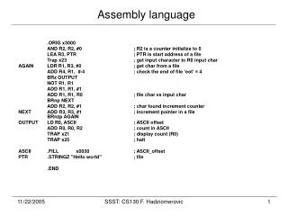
Printing ! to the Screen • MOV AH,02 ; Interrupt instruction to print • MOV DL,24 ; 24 ASCII code for ‘!’ • INT 21 ; Call the Interrupt 21 • MOV AH,4C; Interrupt instruction to return • INT 21; Call INT 21
Reading Char from keyboard until ‘!’ Assume instruction start at memory address 100 • JMP 108 ; Jump to memory location • MOV AH,02 ; Move 02 Print instruction • MOV DL,07 ; Move 07 into DL to beep • INT 21 ; Call Interrupt 21 • MOV AH,01 ; Move 01 Read Char from keyboard • INT 21 ; Call Interrupt 21 • CMP AL,21 ; Compare if Char is ‘!’ • JNZ 102 ; if not print char and read again • MOV AH,4C ; Move 4C to quit safely • INT 21 ; Call Interrupt • NOP ; NO Operation
Debug –Assembly code in action • A small tool called “debug”, which is included in every windows computer, will show the registers and the assembly language instructions.
Works Cited • Runnion, William C. “Structured Programming in Assembly language for the IBM PC” PWS-KENT –Massachusetts 1998 • Mano & Kime, M.Morris & Charles. “Logic and Computer Design Fundamentals” Prentice Hall – New Jersey 2004 • Hyde, Randall. “The Art of Assembly” No Starch Press- California 2003