Download
1 / 46
460 likes | 598 Views
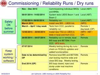
Virgo central interferometer: commissioning and engineering runs. Matteo Barsuglia Laboratoire de l’Accelerateur Lineaire, Orsay. Summary. Introduction The central interferometer Operation with a simple Michelson Operation with a recycled Michelson

E N D
Virgo central interferometer:commissioning and engineering runs Matteo Barsuglia Laboratoire de l’Accelerateur Lineaire, Orsay
Summary • Introduction • The central interferometer • Operation with a simple Michelson • Operation with a recycled Michelson • Operation with the full injection system • E-run programs • Conclusions
Virgo aerial view Pisa
Virgo sensitivity Seismic noise Shot noise Thermal noise
CITF: goals • Test all the tehcnical choice during arm construction: • Suspensions • Fully digital control chain • Output mode-cleaner • Local controls
Suspensions Top stage Last stage Seismic filters
Suspension Control Top stage • Lower suspension stages: • “marionetta” (from upper suspension stage) • mirror (from “reference mass”)
Control Architecture • For each suspension • DSP • correction sharing • Resonance compensation • local controls • DAC 20 bits • Completely digital • LinxOS • C or C++ • photodiode-read-out 20 kHz • Control 10 kHz GPS Timing DOL’s • Photodiodes (powerPC platform): • ADC 16 bits • compression dynamics filters DOL’s • Global control (PowerPC platform): • read phd signals • algorithm for lock acquisition • linear locking and alignment
Local Controls Output mode-cleaner • Completely out of vacuum • CCD camera • Coarse system, markers (50 mrad) • Fine system (laser beam, optical lever) • Control from marionetta (noise filtering)
Detection system Suspended detection bench Output mode-cleaner
Operation with a simple Michelson • Superattenuator controllability • Hierarchical control • Digital control chain • Output mode-cleaner • Control robustness
Suspension performances • No excitation of unwanted degrees of freedom • High robustness to non stationnary noises • Passive filtering experiment (see Braccini’s talk)
Force applied to mirror No feedback to top stage 3.5 mN with feedback to top stage Michelson locking with top stage Slow corrections (f < 70 mHz) Fast corrections (f > 70 mHz)
Control robustness • Results from E0 run (72 hours) : ITF continuouslylocked on • dark fringe for more than 51h • 1 unexpected loss of locking, duty cycle > 0.98 % unlocked (bright fringe) 51 hours locked (dark fringe)
OMC locking on dark fringe Transmitted power TEM00 TEM00 TEM00 TEM00 c2 signal Contrast improvement ~ 10
Operation with a recycled Michelson • Lock acquisition • Frequency stabilization • Linear alignment
The lock acquisition problem North tunnel • Force needed to stop the mirror (finesse = 250) • maximum force 40 mN (limited by EM noise) modules storage
Strategy (I) - enlarge the acting time North tunnel • Widening the error signal Pr_B5_ACq p (Pr_B5_DC) • Use of an antisymetric trigger few % close > 50 % open modules storage
A simulated lock acquisition recycling speed Dark fringe speed trigger WI correction ITF internal power PR correction
A real lock acquisition ITF internal power Dark fringe power Correction PR Correction WI
Frequency stabilization • crossover ~ 3 Hz • very aggressive filtering above 13 Hz
Linear alignment - results ugf ~ 5-10 Hz
Acquisition detection switch • Dark fringe control switched from B1p to B1 • Offset between B1p and B1 • dark fringe on B1p dark fringe on B1 • Need offset compensation and smooth transition
Optical characterization • Input power ~ 2 - 2.5 Watts • Recycled power (maximum) ~ 240 Watts • Not coupled light ~ 30 % • Interferometer contrast: • ~ 5 10-4 (before OMC) , • ~ 5 10-5 (after OMC)
Alignment control noise Laser frequency noise E4 sensitivity
High frequency noise Peaks: mirrors + holders Laser frequency noise
Intermediate range noise • mode-cleaner mass TF • no common mode loop
CITF e-run program • 5 e-runs (september 2001-july 2002) • 72 hours each • 8 hours shift • 4 people in shift (1 ITF, 1 laser/injection, DAQ, 1 learner) • 12 on call sub-system experts • central building closed, remote control
Lock robustness during e-runs Run #losses (in ‘normal’ operation) duty cycle longest lock E0 1 (local ctrl fail) 98% ~ 51 h E1 1 (local ctrl fail) 85%~ 27 h E2 3 (2 ctrl software, 1 vacuum) 98%~ 41 h E3 4 (1 ctrl software, 3 ctrl tuning) 98%~ 40 h E4 4 (2 ctrl software, 2 injection) 73% ~ 14 h Normal operation = no experiments, no special conditions, no calibration
Data acquisition during e-runs • 20 kHz • 2 writing processes in paralles • ~ 4 Mbytes/sec • 1 Tbyes/e-run • 3 kind of data streams: • 20 kHz frames • 50 Hz • Trend (1 Hz)
Run overview – E4 (July 2002) calibration and other special investigations ~ 7 hours calibration ~ 3 h 30’ « stable » operation ~ 61 h 30’
Duty Cycle – E4 • Normal operation ~ 61h 30’ • Locked ~ 42h 20’ • Duty cycle ~ 73 % • 6 streams with CITF locked • longest (5) ~ 14h 30’ • shortest (3) ~ 55’ 4 6 2 1 3 5 Duty cycle limited by lock acquisition problems of retroreflected light from ITF to injection system
Investigation groups • Sources of lock losses • Suspension motions • Angular drifts • Output mode-cleaner • Calibration • Angular noise • Seismic noise • Acoustic noise • Noise gaussianity/stationarity • Glitches • Lines identification • Injection system noise
Lock losses study - example 1 sec • burst in the local controls of IB
Locking accuracy Offset = 4 ·10 -14 Rms = 1 ·10 -12 Offset = 1 ·10 -11 Rms = 9 ·10 -12
Conclusions - sensitivity • Solutions for frequency noise • Replace MC suspension • Add “common mode” loop • Solution for alignment noise • automatic alignment • filtering of high frequency noise
Conclusions - I • Technical choices validated • superattenuators • “out of vacuum” local controls with CCD cameras • digital control chain • output mode-cleaner and detection system • Lot of experience • E-runs program very useful for detetector characterisation
Virgo Planning • Now: • large mirror installation • vacuum leak tests • new MC suspension • local control improvements