Download
1 / 4
40 likes | 61 Views
Last updated 06/11/19. Dynamixel XL-320 to LEGO NXT Connection. Preamble: The LEGO NXT’s Port 4 is a RS-485 serial port. RS-485 operates at +/-12 Volts. However the Dynamixel XL-320 operates its serial lines on TTL (i.e. 0 to 5 Volt) levels. As such, a TTL-to-RS485 converter is used.

E N D
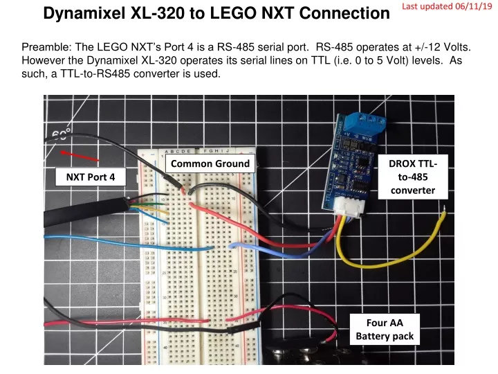
Last updated 06/11/19 Dynamixel XL-320 to LEGO NXT Connection Preamble: The LEGO NXT’s Port 4 is a RS-485 serial port. RS-485 operates at +/-12 Volts. However the Dynamixel XL-320 operates its serial lines on TTL (i.e. 0 to 5 Volt) levels. As such, a TTL-to-RS485 converter is used. Common Ground DROX TTL-to-485 converter NXT Port 4 Four AA Battery pack
Last updated 06/11/19 Step 1: 6 Volt Motor (Dynamixel XL-32) Voltage wiring Note: Work with XL-320 Right side connector. Datasheet of XL-320 shows pins connections. http://emanual.robotis.com/docs/en/dxl/x/xl320/#control-table-of-eeprom-area NB: left figure is from Top i.e. looking into the servo horn Servo Horn • Insert jumper wires into the XL-320’s Molex connector. Connect red jumper to battery 6v, connect black jumper to common ground. Not connected RED Jumper BLK Jumper Common GND +6V to XL-320 pin2 Battery GND to common GND
Last updated 06/11/19 Step 2: DROX to Dynamixel XL-320 (TTL) Wiring DROX Pinout diagram https://www.droking.com/ttl-to-rs485-module-dc-3.0v-30v-rs485-to-ttl-mutual-conversion-hardware-automatic-flow-control-module-converter-module?search=ttl%20to%20rs485&description=true DROX GND wire (BLK) DROX Vcc wire (RED) • Blue from DROX RXD connects to XL-320 Pin 3 (Data) • Black from DROX GND to breadboard common ground. To XL-320 DATA Pin 3 (BLU) DATA to TXD: YLW Jumper GNDs tied to Breadboard GND
Last updated 06/11/19 Step 3: DROX to NXT Wiring (RS-485) • Splice NXT cable • Connect YLW (SCL), BLU (SDA) and BLK (GND) wires into the DROX screw terminal from breadboard using jumper. • Connect GRN (+5v) to DROX red wire. To DROX RS485 Ground To DROX Vcc To DROX B- To DROX A+ DROX (A+) to NXT (SDA Pin 6) DROX (B-) to NXT (SCL Pin 5) DROX (GND) to NXT (GND Pin 2)