Download
1 / 37
380 likes | 552 Views
Architecture and Evaluation of an Unplanned 802.11b Mesh Network. John Bicket, Daniel Aguayo, Sanjit Biswas, and Robert Morris MIT Computer Science and Artificial Intelligence Lab Presented by Anuradha Kadam February 6, 2007. Outline. Introduction Roofnet Design Evaluation Network Use

E N D
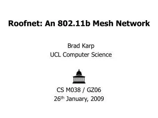
Architecture and Evaluation of an Unplanned 802.11b Mesh Network John Bicket, Daniel Aguayo, Sanjit Biswas, and Robert Morris MIT Computer Science and Artificial Intelligence Lab Presented by Anuradha Kadam February 6, 2007
Outline • Introduction • Roofnet Design • Evaluation • Network Use • Conclusion
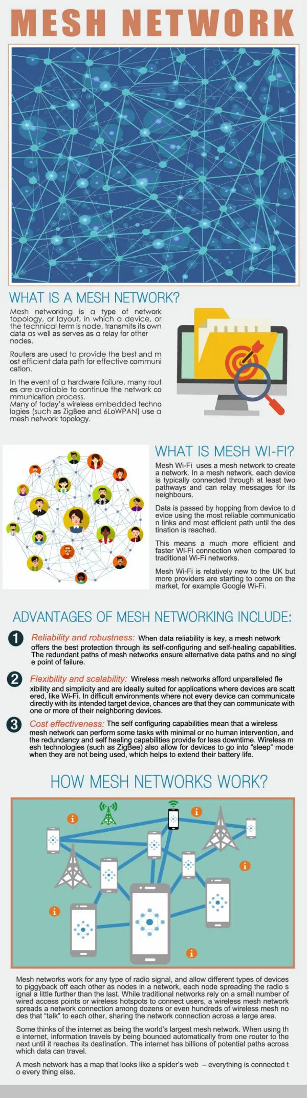
Introduction • Community wireless networks: • Multi-hop network with nodes in chosen locations and directional antennas • Require well-coordinated groups with technical expertise, result in good connectivity and throughput • Hot-spot access points to which clients directly connect • Do not require much coordination to deploy and operate, not as much coverage per wired connection. • Best characteristics of both network types.
Introduction • Unconstrained node placement • Omni-directional antennas • Multi-hop routing • Optimization of routing for throughput • Roofnet
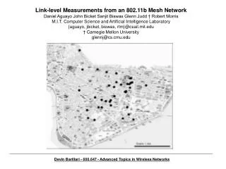
Roofnet Design • 37 nodes spread over four square km • Each node hosted by a volunteer • Most buildings are 3 or 4 story
Hardware • Node: PC, an 802.11b card and roof-mounted omni-directional antenna • PC’s ethernet port provides Internet service to user • 802.11b card based on Intersil Prism 2.5 chip-set • RTS/CTS disabled, pseudo-IBSS mode
Software and Auto-configuration • Each node: Linux, routing software implemented in Click, a DHCP server, a web server • Software is pre-installed. • Node acts as like a cable or DSL modem • User connects PC or laptop to the node’s ethernet interface • Node automatically configures user’s computer via DHCP • Lists itself as default IP router
Addressing • Roofnet carries IP packets inside its own header format and routing protocol • Node: chooses address whose low 24 bits are low 24 bits of node’s Ethernet address and high 8 bits are an unused class-A IP address. • Same address at both the Roofnet and IP layers • These addresses are meaningful only inside Roofnet • Allocates addresses from 192.168.1.x to users • NAT between Ethernet and Roofnet
Gateways and Internet Access • Each node on startup asks for an IP address as a DHCP client. • If it succeeds, the node advertises itself as an Internet gateway. • Gateway acts as NAT for connections from Roofnet to the Internet. • Node selects gateway to which it has the best route metric. • Four Internet gateways
Routing Protocol • Srcr - find highest throughput route between pair of nodes • Omnidirectional antennas give choice of links • Dynamic source-routing (DSR) • Each node maintains partial database of link metrics • Dijkstra’s algorithm
Routing Protocol • Link metric learning: • Node includes link’s current metric in packet’s source route • DSR-style flooded query • Overheard queries and responses
Routing Protocol • Combination of link-state and DSR-style on demand querying • Roofnet gateway floods dummy query • Node sends data to a gateway – gateway learns about links back to the node • Nodes do not need to send flooded queries
Routing Protocol • Flooded queries often do not follow best route • Srcr solution – compute best route from database • Link conditions change leading to change in best route • Notification of failed link sent back to source • New metric information sent to source
Routing Protocol • Source re-runs Dijkstra’s algorithm • Better metric information: • Sources learn through dummy queries from gateways or • Unsolicited link metric information about nearby links
Routing Metric • Srcr uses Estimated Transmission Time (ETT) metric • ETT predicts total amount of time needed to send data packet along a route • Srcr chooses route with lowest ETT
Routing Metric • “Srcr predicts that a link’s highest-throughout bit-rate is the bit-rate with the highest product of delivery probability and bit-rate.” • 1500-byte periodic broadcasts at each available 802.11 bit rate • Periodic minimum-size broadcasts at 1Mbps
Routing Metric • “ETT metric for a link is the expected time to send a 1500 byte packet at that link’s highest throughput bit-rate.” • ETT metric for a route is the sum of the ETTs for the route’s links. • t = 1 / Σi 1/ti t = route’s end-to-end throughput ti = throughput of route’s hop
Bit-Rate Selection • SampleRate: Roofnet’s algorithm to choose among 802.11b transmit bit rates. • Adjusts bit-rate as it sends data packets over a link • Adjusts choice more accurately and quickly than ETT • Bases choice on actual data transmission v/s on periodic broadcast probes • Sends packets at bit-rate which currently provides highest throughput
Evaluation • Method • Basic Performance • Link Quality and Distance • Effect of density • Mesh Robustness • Architectural Alternatives • Inter-hop Interference
Method • Multi-hop TCP data set • 84-byte pings once per second for 10 seconds • Route established and latency measured • Throughput = number of bytes delivered to receiving application • 10% pairs: no working routes • Single-hop TCP data set • Measure throughput on direct radio link between pair of nodes
Method • Loss matrix data set • Measure loss rate between pair of nodes • 1500-byte broadcasts at each 802.11b bit-rate • Multi-hop density data set • Measure throughput between fixed set of four nodes • Vary number of nodes participating in routing • Some of the analyses involve simulated route throughput calculated from the single-hop TCP.
Basic Performance Average throughput is 627 kbits/sec
Basic Performance TCP throughput to each node from its chosen gateway
Link Quality and Distance • Srcr favors short links of a few hundred meters. • Fast, short hops are the best policy
Link Quality and Distance • Median = 0.8 • Single-hop route with 40% loss can deliver more data than a two-hop route with perfect links.
Effect of density • “Mesh networks are effective only if the node density is sufficiently high.” • Simulate different size subsets of Roofnet • Estimate multi-hop throughput between pairs in the subset
Mesh Robustness Most nodes have many neighbors Majority of nodes use many neighbors Roofnet makes good use of the mesh architecture in ordinary routing
Mesh Robustness • Extent to which network is vulnerable to loss of its most valuable links • Dozens of the best links must be eliminated before throughput is reduced by half.
Mesh Robustness • Effect on throughput of cumulatively eliminating the best-connected nodes. • Best two nodes are important for performance.
Architectural Alternatives: Optimal Choice • Comparison with single-hop (access point) network. • Single-hop: 5 gateways to cover all nodes • Multi-hop forwarding provides higher average throughput • Sequence of short high quality links
Architectural Alternatives: Random Choice • If Roofnet were single-hop, 25 gateways would be required to cover all nodes. • Multi-hop routing improves connectivity and throughput. • Careful gateway choice improves throughput for both multi-hop and single-hop routing.
Inter-hop Interference • Measured multi-hop throughput lower than expected. • Concurrent transmissions on different hops collide and cause packet loss.
Inter-hop Interference • 802.11 RTS/CTS mechanism: prevent collisions • RTS/CTS does not improve performance
Network Use • Measurements of user activity on Roofnet • One of the four gateways monitored packets forwarded between Roofnet and the Internet. • In one 24-hr period: Average of 160 kbits/sec • Gateway’s radio busy 70% of the monitoring period • Less than 1% UDP. Rest were TCP. • 16 Roofnet nodes accessed the Internet
Conclusion • Ease of deployment • 37 nodes in one year with little administrative or installation effort • Average throughput = 627 kbits/sec • Position of internet gateways determined by convenience • Multi-hop mesh increases both connectivity and throughput