Download
1 / 48
480 likes | 784 Views
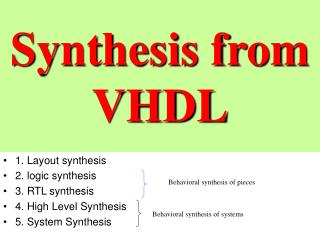
VHDL Synthesis in FPGA. By Zhonghai Shi February 24, 1998 School of EECS, Ohio University. Agenda. Getting Started with VHDL VHDL Coding Hint VHDL Coding in FPGAs Floorplanning the Design Building Design Hierarchy Understanding High Density Design Flow. Getting Started with VHDL.

E N D
VHDL Synthesis in FPGA • By Zhonghai Shi • February 24, 1998 • School of EECS, Ohio University
Agenda • Getting Started with VHDL • VHDL Coding Hint • VHDL Coding in FPGAs • Floorplanning the Design • Building Design Hierarchy • Understanding High Density Design Flow
Getting Started with VHDL • VHDL? • Understanding HDL Design Flow for FPGAs
Getting Started with VHDL • Advantages of Using HDLs to Design FPGAs • Top-Down Approach for Large Projects • Functional Simulation Early in the Design Flow • Automatic Conversion of HDL Code to Gates • Type Checking • Early Testing of Various Design implementations
Getting Started with VHDL • Software Requirements
HDL Coding Hints • Comparing Synthesis and Simulation Results • Omit the Wait for XX ns Statement • wait for XX ns; • Omit the ...After XX ns Statement • Q <=0 after XX ns;
HDL Coding Hints • Order and Group Arithmetic Functions • ADD <= A1 + A2 + A3 + A4; • ADD <= (A1 + A2) + (A3 + A4); • Omit Initial Values • variable SUM: INTEGER :=0;
HDL Coding Hints • Selecting VHDL Coding Styles • Selecting a Capitalization Style • Using Labels • Using Named and Positional Association • Creating Readable Code • Using Std_logic Data Type
HDL Coding Hints • Using Schematic Design Hints with HDL Designs • VHDL Design ofBarrel Shifter Design • implemented using 16 16-to-1 multiplexers, one for each output. • 20-input function requires at least 5 logic blocks • 16 x 5 = 80 logic blocks • implemented using 32 4-to-1 multiplexers arranged in two levels of sixteen. • 32 x 1 = 32 logic blocks
HDL Coding Hints • Resource Sharing & Gate Reduction
HDL Coding Hints • Using If Statements, Using Nested_If Statements • Using Case Statements
HDL Coding for FPGAs • latches vs. flip-flop • in Xilinx FPGAs: • 2 FFs/CLB which can be used • latches requires FG function generator • using latch ... if (write = ‘1’ ) then stored_value <= value_in; end if; ...
HDL Coding for FPGAs • Latches vs. flip-flops • using flip-flop ... if (write’event and write = ‘1’) then stored_value <= value_in; end if; ...
HDL Coding for FPGAs • Encoding State Machines • Using Binary Encoding • Using Enumerated Type Encoding • Using One-Hot Encoding • Better suited for use with the fan-in limited and flip-flop-rich architecture of FPGA
HDL Coding for FPGAs • Comparing Synthesis Results for Encoding Styles
HDL Coding for FPGAs • Implementing Multiplexers with Tristate Buffers • Use internal tristate buffers (BUFTs) to implement multiplexers larger than 4-to-1. • Can vary in width with only minimal impact on area and delay • Can have as many inputs as there are tristate buffers per horizontal longline in the target device • Have one-hot encoded selector inputs
Floorplanning Your Design • Using the Floorplanner • Creating a MAP File • Using Xmake • Using PPR • Using Prep for Floorplanner Command
Floorplanning Your Design • Deciding What Elements to Floorplan • Large objects such as RPMs, registers, counters, and RAMs • Buses (place all BUFTs and bus elements) • BUFTs with I/O or RPM inputs • Multiple BUFTs (except VCC or GND) with identical source pin inputs
Building Design Hierarchy • Building Design Hierarchy • Advantages • Efficiently manage the design flow • Reduces design time by allowing you to use existing design modules more than once • Produce designs that are easy to understand
Building Design Hierarchy • Modifying Design Hierarchy for PPR • Reduces Gate Count • Improves Routability • Reduces Routing Time • Reduces Time Required for Small Design Changes • Reduces Debugging Time
Building Design Hierarchy • Top Design Example
Building Design Hierarchy • Compiling Top Design After Modifying the Hierarchy • R0 block uses approximately 591 CLBs • X0 block uses approximately 342 CLBs • UP0 block uses approximately 25 CLBs • DD0 block uses approximately four CLBs
Building Design Hierarchy • Compiling Top Design After Modifying the Hierarchy
Building Design Hierarchy • Comparing Top Design Methodologies • Flat Design • densely packed and is unroutable. • Original Design Hierarchy • small changes to this design may make the design unroutable. • Modified Hierarchy
Understanding High-Density Design Flow • Estimating Your Design Size • run PPR on your design after compiling it as one flat module • Determining Device Utilization • Evaluating Your Design for Coding Style and System Features • correct coding style problems • incorporate FPGA system features
Understanding High-Density Design Flow • Modifying Your Design Hierarchy • One flat module vs. many small modules • structure design hierarchy to guide the placement and routing. • Synthesizing and Optimizing Your Design • Use the Synopsys Group command to define the new hierarchy.
Understanding High-Density Design Flow • Use the Synopsys Group command • {M1,M2,M3,M4,M5} -design_name X1 -cell_name X1 • group {M6,M7,M8,M9,M10,M11} -design_name X2 \ -cell_name X2 • group {N7,N8,N9,N10,N11,N12,N13} -design_name R1 \ • -cell_name R1 • group {N2,N3,N4,N5} -design_name R2 -cell_name R2 • group {N6} -design_name R3 -cell_name R3 • group {N1} -design_name R4 -cell_name R4
Understanding High-Density Design Flow • Translating Your Design and Adding Group TimeSpecs • translate your design to an XNF file • adding Timing Specifications • Building Your Design Hierarchy • constrain your design modules to specific device areas in the Floorplanner. • define boundaries in the Floorplan window and place the selected modules within the specified boundaries.
Understanding High-Density Design Flow • Floorplanning Your Design • Placing and Routing Your Design • Using PPR Options • Determining If PPR Can Route Your Design • Evaluating the Results • Evaluating Module Placement with the Floorplanner