Download
1 / 66
1.65k likes | 4.41k Views
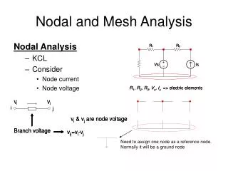
Basic Nodal and Mesh Analysis. Al-Qaralleh. Methods of Analysis. Introduction Nodal analysis Nodal analysis with voltage source Mesh analysis Mesh analysis with current source Nodal and mesh analyses by inspection Nodal versus mesh analysis. Steps of Nodal Analysis.

E N D
Basic Nodal and Mesh Analysis Al-Qaralleh PSUT
Methods of Analysis • Introduction • Nodal analysis • Nodal analysis with voltage source • Mesh analysis • Mesh analysis with current source • Nodal and mesh analyses by inspection • Nodal versus mesh analysis PSUT
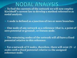
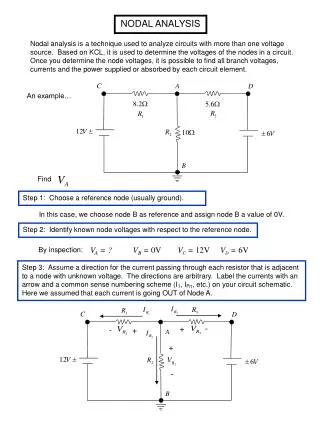
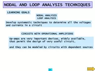
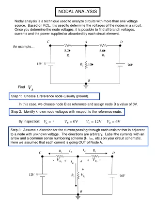
Steps of Nodal Analysis 1. Choose a reference (ground) node. 2. Assign node voltages to the other nodes. 3. Apply KCL to each node other than the reference node; express currents in terms of node voltages. 4. Solve the resulting system of linear equations for the nodal voltages. EEE 202
Common symbols for indicating a reference node, (a) common ground, (b) ground, (c) chassis. PSUT
1. Reference Node The reference node is called the ground node where V = 0 500W 500W + I1 V 1kW 500W I2 500W – EEE 202
Steps of Nodal Analysis 1. Choose a reference (ground) node. 2. Assign node voltages to the other nodes. 3. Apply KCL to each node other than the reference node; express currents in terms of node voltages. 4. Solve the resulting system of linear equations for the nodal voltages. EEE 202
2. Node Voltages V1, V2, and V3 are unknowns for which we solve using KCL 500W 500W V1 V2 V3 1 2 3 I1 1kW 500W I2 500W EEE 202
Steps of Nodal Analysis 1. Choose a reference (ground) node. 2. Assign node voltages to the other nodes. 3. Apply KCL to each node other than the reference node; express currents in terms of node voltages. 4. Solve the resulting system of linear equations for the nodal voltages. EEE 202
Currents and Node Voltages 500W V1 V2 V1 500W EEE 202
3. KCL at Node 1 500W V1 V2 I1 500W EEE 202
3. KCL at Node 2 500W 500W V1 V2 V3 1kW EEE 202
3. KCL at Node 3 500W V2 V3 500W I2 EEE 202
Steps of Nodal Analysis 1. Choose a reference (ground) node. 2. Assign node voltages to the other nodes. 3. Apply KCL to each node other than the reference node; express currents in terms of node voltages. 4. Solve the resulting system of linear equations for the nodal voltages. EEE 202
4. Summing Circuit Solution Solution: V = 167I1 + 167I2 500W 500W + I1 V 1kW 500W I2 500W – EEE 202
Calculus the node voltage in the circuit shown in Fig. 3.3(a) PSUT
At node 1 PSUT
At node 2 PSUT
In matrix form: PSUT
Practice PSUT
At node 1, PSUT
At node 2 PSUT
At node 3 PSUT
In matrix form: PSUT
3.3 Nodal Analysis with Voltage Sources • Case 1: The voltage source is connected between a nonreference node and the reference node: The nonreference node voltage is equal to the magnitude of voltage source and the number of unknown nonreference nodes is reduced by one. • Case 2: The voltage source is connected between two nonreferenced nodes: a generalized node (supernode) is formed. PSUT
3.3 Nodal Analysis with Voltage Sources A circuit with a supernode. PSUT
A supernode is formed by enclosing a (dependent or independent) voltage source connected between two nonreference nodes and any elements connected in parallel with it. • The required two equations for regulating the two nonreference node voltages are obtained by the KCL of the supernode and the relationship of node voltages due to the voltage source. PSUT
Example 3.3 • For the circuit shown in Fig. 3.9, find the node voltages. i2 i1 PSUT
At suopernode 1-2, PSUT
At supernode 3-4, PSUT
3.4 Mesh Analysis • Mesh analysis: another procedure for analyzing circuits, applicable to planar circuit. • A Mesh is a loop which does not contain any other loops within it PSUT
(a) A Planar circuit with crossing branches, (b) The same circuit redrawn with no crossing branches. PSUT
A nonplanar circuit. PSUT
Steps to Determine Mesh Currents: • Assign mesh currentsi1, i2, .., in to the n meshes. • Apply KVL to each of the n meshes. Use Ohm’s law to express the voltages in terms of the mesh currents. • Solve the resulting n simultaneous equations to get the mesh currents. PSUT
Fig. 3.17 A circuit with two meshes. PSUT
Apply KVL to each mesh. For mesh 1, • For mesh 2, PSUT
Solve for the mesh currents. • Use i for a mesh current and I for a branch current. It’s evident from Fig. 3.17 that PSUT
Find the branch current I1, I2, and I3 using mesh analysis. PSUT
For mesh 1, • For mesh 2, • We can find i1 and i2 by substitution method or Cramer’s rule. Then, PSUT
Use mesh analysis to find the current I0 in the circuit. PSUT
Apply KVL to each mesh. For mesh 1, • For mesh 2, PSUT
For mesh 3, • In matrix from becomewe can calculus i1, i2 and i3 by Cramer’s rule, and find I0. PSUT
3.5 Mesh Analysis with Current Sources A circuit with a current source. PSUT
Case 1 • Current source exist only in one mesh • One mesh variable is reduced • Case 2 • Current source exists between two meshes, a super-meshis obtained. PSUT
a supermesh results when two meshes have a (dependent , independent) current source in common. PSUT
Properties of a Supermesh • The current is not completely ignored • provides the constraint equation necessary to solve for the mesh current. • A supermesh has no current of its own. • Several current sources in adjacency form a bigger supermesh. PSUT