Download
1 / 37
370 likes | 588 Views
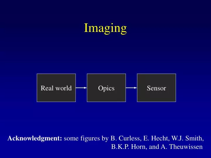
Imaging. Real world. Opics. Sensor. Acknowledgment: some figures by B. Curless, E. Hecht, W.J. Smith, B.K.P. Horn, and A. Theuwissen. Optics. Pinhole camera Lenses Focus, aperture, distortion Vignetting Flare. Pinhole Camera. “Camera obscura” – known since antiquity

E N D
Imaging Real world Opics Sensor Acknowledgment: some figures by B. Curless, E. Hecht, W.J. Smith, B.K.P. Horn, and A. Theuwissen
Optics • Pinhole camera • Lenses • Focus, aperture, distortion • Vignetting • Flare
Pinhole Camera • “Camera obscura” – known since antiquity • First recording in 1826 onto a pewter plate (by Joseph Nicephore Niepce)
Pinhole Camera Limitations • Aperture too big: blurry image • Aperture too small: requires long exposure or high intensity • Aperture much too small: diffraction through pinhole blurry image
Lenses • Focus a bundle of rays from a scene point onto a single point on the imager • Result: can make aperture bigger
Ideal Lenses • Thin-lens approximation • Gaussian lens law: • Real lenses and systems of lenses may be approximated by thin lenses if only paraxial rays (near the optical axis) are considered 1/do + 1/di = 1/f
Monochromatic Aberrations • Real lenses do not follow thin lens approximation because surfaces are spherical (manufacturing constraints) • Result: thin-lens approximation only valid iff sin
Monochromatic Aberrations • Consider the next term in the Taylor series, i.e. sin - 3/3! • “Third-order” theory – deviations from the ideal thin-lens approximations • Called primary or Seidel aberrations
Spherical Aberration • Results in blurring of image, focus shifts when aperture is stopped down • Can vary with the way lenses are oriented
Coma • Results in changes in magnification with aperture
Petzval Field Curvature • Focal “plane” is a curved surface, not a plane
Distortion • Pincushion or barrel radial distortion • Varies with placement of aperture
Distortion • Varies with placement of aperture
Correcting for Seidel Aberrations • High-qualitycompound lensesuse multiplelens elements to“cancel out”these effects • Often 5-10 elements,more for extreme wide angle
Catadioptrics • Catadioptric systems use bothlenses and mirrors • Motivations: • Systems using parabolic mirrors can be designed to not introduce these aberrations • Easier to make very wide-angle systems with mirrors
Other Limitations of Lenses • Flare: light reflecting(often multiple times)from glass-air interface • Results in ghost images or haziness • Worse in multi-lens systems • Ameliorated by optical coatings (thin-film interference)
Other Limitations of Lenses • Optical vignetting: less power per unit area transferred for light at an oblique angle • Transferred power falls of as cos4 • Result: darkening of edges of image • Mechanical vignetting: due to apertures
Sensors • Vidicon • CCD • CMOS
Vidicon • Best-known in family of “photoconductive video cameras” • Basically television in reverse + + + + Scanning Electron Beam Electron Gun Lens System Photoconductive Plate
Digression: Gamma • Vidicon tube naturally has signal that varies with light intensity according to a power law with gamma 1/2.5 • CRT (televisions) naturally obey a power law with gamma 2.5 • Result: standard for video signals has a gamma of 1/2.5
MOS Capacitors • MOS = Metal Oxide Semiconductor Gate (wire) SiO2 (insulator) p-type silicon
MOS Capacitors • Voltage applied to gate repels positive “holes” in the semiconductor +10V + + + + + + Depletion region (electron “bucket”)
MOS Capacitors • Photon striking the material creates electron-hole pair +10V Photon + + + + + + +
Charge Transfer • Can move charge from one bucket to another by manipulating voltages
Charge Transfer • Various schemes (e.g. three-phase-clocking) for transferring a series of charges along a row of buckets
CCD Architectures • Linear arrays • 2D arrays • Full frame • Frame transfer (FT) • Interline transfer (IT) • Frame interline transfer (FIT)
Linear CCD • Accumulate photons, then clock them out • To prevent smear: first move charge to opaque region, then clock it out
Full-Frame CCD • Problem: smear
CMOS Imagers • Recently, can manufacture chips that combine photosensitive elements and processing elements • Benefits: • Partial readout • Signal processing • Eliminate some supporting chips low cost
Color • 3-chip vs. 1-chip: quality vs. cost
Chromatic Aberration • Due to dispersion in glass (focal length varies with the wavelength of light) • Result: color fringes near edges of image • Correct by building lens systems with multiple kinds of glass
Correcting Chromatic Aberration • Simple way of partially correcting for residual chromatic aberration after the fact: scale R,G,B channels independently