Download
1 / 33
330 likes | 576 Views
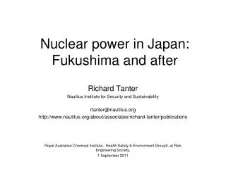
The 2nd Research Co-ordination Meeting on Behaviour of Cementitious Materials in Long Term Storage and Disposal of Radioactive Waste Bucharest, Romania. Long-term Behavior of Cementitious Materials in the Korean Repository Environment (Research Agreement No. 14246).

E N D
The 2nd Research Co-ordination Meeting on Behaviour of Cementitious Materials in Long Term Storage and Disposal of Radioactive Waste Bucharest, Romania Long-term Behavior of Cementitious Materials in the Korean Repository Environment(Research Agreement No. 14246) Joo Wan Park and Chang Lak Kim Korea Hydro & Nuclear Power Co., Ltd. (KHNP) Nuclear Engineering & Technology Institute (NETEC) KHNP-NETEC
Today…… • Background • - Briefs on LILW Management & National Disposal Project • Objectives & Scope • Overall Implementation Plan • Research Work Done & Results KHNP-NETEC 2
Nuclear Energy in Korea (As of November 2008) • Commercial operation of Gori Unit #1 began in 1978 • Currently total 20 NPPs (16 PWRs and 4 CANDUs) in commercial operation • 6 under construction • 2 currently in planning • Nuclear share of electricity 38.6 % Seoul Uljin Wolsong LILW Disposal Center Wolsong & Sinwolsong Daejeon Yonggwang In operation ( CANDU Under construction Gori Planned 3
Location Number of Reactors Storage Capacity(drums) Cumulative amount(drums) Kori 4 50,200 35,560 Yonggwang 6 23,300 16,454 Ulchin 6 17,400 12,877 Wolsong 4 9,000 6,035 TOTAL 99,900 70,926 LILW Management • Arising of LILW from: • Application of RI and Operation of NPP • Amount of radioactive waste storage (As of Dec. 2007): KHNP-NETEC 4
Status of National LILW Disposal Project • Name: Wolsong LILW Disposal Center • Site Location: Gyeongju (South Eastern Part of Korean Peninsula) • Area: 2,096,491 m2 (2.1 Mm2) • Capacity: 100, 000 drums (Phase I), 800,000 drums (Final) • Disposal Type: Silo type disposal (PhaseI) • Project Duration: ’06. 1 ~ ’10. 6 • License: Approved for Construction & Operation by MEST • (Regulatory Authority) on July 2008 • Construction: Started on August 2008 KHNP-NETEC 5
A Bird’s Eye View of Wolsong Site KHNP-NETEC 6
Concept of Surface Facility and Disposal Silos Surface facilities Vertical shaft C/T O/T Entrance portal of C/O tunnels 6 Silos for phase 1 KHNP-NETEC 7
Concept of Surface Facility and Disposal Silos Operational Tunnel Vertical Shaft Disposal Silos Construction Tunnel KHNP-NETEC 8
Crushed Rock Concrete Overpack Crushed Rock Concrete Plug Concept of Facility Closure KHNP-NETEC 9
Objectives and Scope Objectives • To investigate the closure concepts and cementitious backfill materials for the facility closure. • To gain practical experiences in major issues considered in closure concept of the Korean LILW repository. Scope • Characterization of concrete container and cementitious backfill • materials in the Korean LILW repository • Development of repository closure concept and evaluation of long-term • behavior of cementitious materials • Radionuclide transport modeling considering concrete degradation in • repository conditions KHNP-NETEC 10
Overall Implementation Plan • Year 1 • Characterization of concrete container and cementitious backfill materials in the Korean LILW repository • Packaging consideration for disposal in silo type repository • Investigation of backfill materials for repository closure • Performance test for physico-chemical properties of backfill materials • Year 2(On-going) • Development of repository closure concept and evaluation of long-term behavior of cementitious materials • Establishment of closure concept for unit silo and disposal facility • Evaluation of gas generation and migration in disposal silo • Degradation modeling of concrete structure and/or backfill materials KHNP-NETEC 11
Overall Implementation Plan • Year 3 • Radionuclide transport modeling considering concrete degradation in repository conditions • Development of conceptual models for intact and degraded conditions • Implementation of input parameter database and quality assurance for safety/performance assessment • Safety/performance assessment of disposal facility using a proprietary computer tool KHNP-NETEC 12
Research Work Done & Results • Laboratory Test of Cementitious Backfill Materials • Gas Generation & Migration Studies • Degradation Modeling of Concrete Structure • Comparison of Silo Closure Option in the Site-specific • Condition KHNP-NETEC 13
Lab. test of cementitious backfill materials • Composition of cement mortars • Test methods • Hydraulic conductivity where k : hydraulic conductivity (m/s), Q : flux per unit time(㎥/s), A:cross-sectional area of specimen(㎡), P : water pressure(kg/㎡), l : thickness of specimen (m), m : unit mass of water (㎏/㎥). • Gas permeability where K : gas conductivity (m/s), P1 : inlet pressure(kg/㎡), P2 : atmospheric pressure(kg/㎡), h: thickness of specimen (m), Q : gas flow rate(㎥/s), A : Area(㎡), γ : gas unit mass /volume(kg/㎥). KHNP-NETEC 14
Test results Hydraulic conductivity of various mixing conditions of cement mortar KHNP-NETEC 15
Gas Generation in a Silo • Metal corrosion, Microbial degradation : GAMMON (UKAEA) • Radiolysis : MAXH2 (KHNP) • DAW, 200 L Steel Drum, 16700 Drums in a Silo Gas generation rate due to metal corrosion Gas generation due to microbial degradation • Most of gas generation comes from metal corrosion in the form of H2. • After 1,000 yrs, H2 gas generation is about 9.0×10⁴ m3 . • Gas generation is rapidly increased immediately after closure. KHNP-NETEC 16
Gas Migration Study (On-going) • TOUGH-II simulation • Sensitivity analysis • - gas gen. rate, material(concrete, • host rock) properties Vertical cross section and mesh of the model domain and seven monitoring points used in the numerical simulations Temporal change of mass fraction of gas dissolved in groundwater at the seven monitoring points in the model domain Spatial distribution of gas pressure in the model domain after 1000 years of hydrogen gas generation from the radioactive waste KHNP-NETEC 17
Gas Migration Study (On-going) • Sensitivity Analysis Results Spatial distribution of mass fraction of gas dissolved in groundwater in the model domain after 1000 years of hydrogen gas generation: (a) Case 1: gas gen. rate x 2 (b) Case 2: hyd. cond. of concrete x 0.1, (c) Case 3: hyd. cond. of host rock x 2, (d) Case 4 : case1 + case. KHNP-NETEC 18
Degradation Modeling of Concrete Structure • Concrete degradation factors considered • Sulfate and Mg Attack => Expansive Force, Crack and Spalling • Ca(OH)2 Leaching => reduce the pH, promote the corrosion of reinforcing steel • Alkali-Aggregate Reaction => Crack formation in concrete • Chloride Attack & Carbonation => Oxidation due to Cl ion penetration, Neutralization (pH 12 • 8), Enhancement of Ca(OH)2 leaching in low pH condition KHNP-NETEC 19
Corrosion of Reinforcing Steel Cracking of Concrete Porosity and hydraulic permeability increase 4th step Volume increase Corrosion Phase 2 Propagation period 3rd step Depassivation Above threshold level 2nd step Carbonation Chloride attack Concrete Neutralization Phase 1 Initiation period 1st step KHNP-NETEC 20
Service Life Models • Diffusion Model => Migration of chemical species only by diffusion in concrete • Empirical Model=> Empirical mathematical models (US DOE) • Reactive-Transport Model => Migration of chemical species by advection and dispersion • => Complex chemical reaction models and thermodynamic data • Diffusion model and empirical model are considered in this stage. KHNP-NETEC 21
Analytical solution of diffusion equation Phase I Power function Evaluation of Concrete Degradation • Effect of α value on chloride diffusion in diffusion model KHNP-NETEC 22
Corrosion rate of reinforcing steel Evaluation of Concrete Degradation • Corrosion Rate of Reinforcing Steel in diffusion model Phase II DO Conc.: 0.24 mg/L, DO diffusion coeff.: 2×10⁻⁸ cm2/yr KHNP-NETEC 23
Corrosion onset time (Phase I) Corrosion time (Phase II) 10-5 m/yr Evaluation of Concrete Degradation • Effect of w/c ratio in empirical model KHNP-NETEC 24
Comparison of Silo Closure Option • 5 Option for a Silo Closure • Groundwater Flow Analysis – Regional & Local Models • Radionuclide Transport Assessment KHNP-NETEC 25
SiloClosure Option Host Rock Concrete Concrete Host Rock Crushed Rock Crushed Rock Radioactive waste + Crushed rock Radioactive waste + Crushed rock CASE1-M1 CASE1-M2 Crushed Rock Cement Mortar Concrete Host Rock Host Rock Concrete Host Rock Concrete Crushed Rock Crushed Rock Crushed Rock Radioactive waste + Crushed rock Radioactive waste + Crushed rock Radioactive waste + Crushed rock CASE2-M1 CASE2-M2 Bentonite Crushed Rock CASE2-M3 Bentonite(10%)+Sand(90%) KHNP-NETEC 26
Groundwater Flow Modeling - Regional 48.2m 2.18km 32.5m 41.0m General head Boundary 41.5m 25.5m 25.6m River boundary A A’ 36.5m 1.62km 19.3m Visual Modflow 3D 0.7km SILO A A’ KHNP-NETEC 27
200m A A ’ 200m Groundwater Flow Modeling - Local 155m A A ’ Crushed Rock (24mx24mx15m) Outer (width: 1.2m) Radioactive waste + Crushed Rock (24mx24mx35m) Inner (width: 0.2m) Concrete (width : 0.6~1.2m) Visual Modflow 3D KHNP-NETEC 28
Groundwater Infiltration into a Silo Intact Concrete After Fully Degraded KHNP-NETEC 29
Radionuclide Transport Assessment • Reference Scenario KHNP-NETEC 30
Radionuclide Transport Assessment • Conceptual Model The connection symbol “” denotes advective mass transfer, while the symbol “↔” denotes diffusive/dispersive mass transfer from one compartment to another compartment, respectively • Mathematical Modeling : Compartment model • Assessment Tool : MOSAIC developed by KHNP & MSCI KHNP-NETEC 31
Comparison of NF Release Rate KHNP-NETEC 32
Thank you for your attention! KHNP-NETEC