Download
1 / 25
270 likes | 331 Views
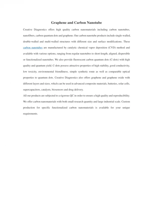
This project delves into the world of carbon nanotube electronics for biosensors, gas sensing, and protein studies. The research includes modeling CNT devices, testing SiO2 deposition methods, and etching metal dots from chip surfaces. The ultimate goal is to create oxide-covered nanotube devices that utilize defect sites effectively. The research involves CVD growth of nanotubes on silicon wafers, electrode deposition for measuring nanotube wires, and studying nanotube devices with defects. Techniques such as COMSOL modeling, E-Beam evaporation, and BMR PECVD are explored for oxide film deposition. Challenges with metal dot etching and characterizing oxide films are addressed for future study.

E N D
Carbon Nanotube Electronics Presented By: Yu-Jin Chen Mentor: Professor Philip Collins IM-SURE 2007
My Work: • COMSOL model of a CNT device • Tested two methods of depositing SiO2: • Electron beam evaporation (E-Beam) • Plasma-enhanced chemical vapor deposition (PECVD; BMR) • Also tested etching metal dots from the surface of a chip (with and without oxide)
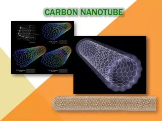
Carbon Nanotubes • A carbon nanotube can be modeled as a hexagonal lattice (graphene) “rolled up” into a cylinder. • The nanotubes we work with are single-walled and typically 1 nm in diameter.
sensitive to gases Motivation modified for biosensing • The Collins Group researches carbon nanotubes because there are potential applications for biosensors, sensing dangerous gases, studying proteins, etc.
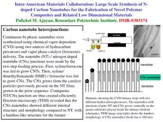
Nanotube Devices • The carbon nanotubes are grown on silicon wafers by chemical vapor deposition (CVD). • Lithographically-deposited electrodes allow us to measure nanotube wires and transistors.
CNT Devices: Typical Device Sizes ~10 um ~150 um ~1 um
Nanotubes with Defects • Defects can be added to a nanotube and the defects can be chemically modified. • Defects are important because they are very sensitive to changes in the environment.
The Big Picture • First, we have a device with a metal dot deposited on the nanotube sidewall. • Next, we deposit oxide on this device. • Finally, we etch the metal dot, and are left with a nanotube device that has an isolated defect. • The ultimate goal is to develop a working recipe for making oxide-covered nanotube devices that take advantage of the sites of defects.
COMSOL • The model consists of a silicon substrate, a silicon oxide layer, two titanium electrodes and 105 cylindrical segments that represent the nanotube.
E-Beam Evaporator • This uses an electron beam to evaporate materials (silicon oxide in our case). The resulting gas then expands from the crucible and hits the sample mounted at the top of the machine. • This method is very controllable, capable of depositing a film 1 Angstrom thick.
BMR PECVD • The BMR PECVD system flows gases into a chamber containing our sample. Then, a plasma is created, which causes the other gases to react, forming oxide. The oxide then sticks to the surface of the sample. • This method creates a very uniform and dense film.
Comparing Oxides • Initial tests showed that the BMR film was much better in quality compared to the E-Beam film.
Nanotube Test Results • The results show that the nanotubes survive the electron beam evaporator but not the plasma CVD.
Metal Etch • We use samples in which gold dots have been placed on the surface so that we can test our ability to etch metal dots from under oxide.
Metal Etch Results • The sample on the left has oxide deposited on it. The sample on the right has been etched in aqua regia.
Problems with Etching • The image on the left shows a sample before it was etched. The right image shows the sample after it was etched. In both cases, this was a bare surface with gold dots.
Breaking the Monolayer • We discovered that the monolayer surrounding the particles protected them from etching. • After consulting the literature and other groups, we tried exposing the samples to UV as well as different etching solutions to solve this problem. However, we have not had success. λ= 365 nm Au
Summary • What we can do: • Deposition of metal dots on defects • Controlled deposit of very thin oxide films • Etch very large metal dots from under oxide • Future work: • Adding more to the COMSOL model • More tests to etch away metal nano-dots • Characterizing the oxide films deposited by e-beam evaporation
Collins Group: Professor Phil Collins Alex Kane Bucky Khalap Brett Goldsmith John Coroneus* Danny Wan Steve Hunt Tatyana Sheps Phil Haralson Images courtesy of the Collins Group and the INRF website. INRF: David Crosley Vu Phan IM-SURE: Said Shokair The NSF and UROP Special Thanks
Electronic Properties • Carbon nanotubes act as one-dimensional wires. They can be either metallic or semiconducting depending on the chirality of the tube, the “twist” of the hexagonal lattice.
Chirality • The chiral vector for a (2,4) nanotube (left) and an unrolled (5,0) nanotube with one unit cell highlighted in red.
Gate Electrode • The gate electrode is capacitively coupled to the nanotube, so it is able to increase or decrease the number of charge carriers in a semiconducting tube.
Goals • The ultimate goal is to develop a working recipe for making oxide-covered nanotube devices that take advantage of the sites of defects.