Download
1 / 29
290 likes | 304 Views
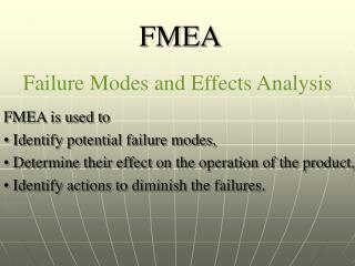
Join us for a panel session discussing the failure modes of DC power systems. Explore topics such as telecom industry standards, power conversion, battery reserves, and surge protection devices.

E N D
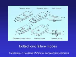
Technical Panel Session. Sunday January 11, 2015.DC System Failure Modes Chair J. Allen Byrne Technical Support and Services Manager Interstate PowerCare A Division of Interstate Batteries IEEE PES SBC Winter Meeting. January 11 – 15, 2014. New Orleans, LA
Technical Panel Session. Sunday January 11, 2014DC System Failure Modes J. Allen Byrne Interstate PowerCare Some Background IEEE PES SBC Winter Meeting. January 11 - 15, 2014. New Orleans LA
Technical Panel Session. Sunday January 11, 2014DC System Failure Modes Curtis Ashton. Century Link . Representing the Telco Industry. IEEE PES SBC Winter Meeting. January 11 - 15, 2014. New Orleans LA
Technical Panel Session. Sunday January 11, 2014DC System Failure Modes Kurt Uhlir Standby Power System Consultants, Inc. J. Allen Byrne Representing the Utilities Industry IEEE PES SBC Winter Meeting. January 11 - 15, 2014. New Orleans LA
Technical Panel Session. Sunday January 11, 2014DC System Failure Modes George Pedersen Btech Representing the Monitoring Industry IEEE PES SBC Winter Meeting. January 11 - 15, 2014. New Orleans LA
Technical Panel Session. Sunday January 11, 2014DC System Failure Modes Rob. Schmitt Representing the Battery Manufacturers. IEEE PES SBC Winter Meeting. January 11 - 15, 2014. New Orleans LA
Technical Panel Session. Sunday January 11, 2014DC System Failure Modes Some Background. J. Allen Byrne IEEE PES SBC Winter Meeting. January 11 - 15, 2014. New Orleans LA
Technical Panel Session. Sunday January 11, 2014DC System Failure Modes Notes. At the Summer Meeting in Newport, RI, The SBC selected the topic “DC System Failure Modes” to be presented as a Sunday Tutorial Session for the Winter Meeting. The first question was how does one define DC Systems? This tutorial will focus on those system where the DC output powers the load. IEEE PES SBC Winter Meeting. January 11 - 15, 2014. New Orleans LA
Why DC Power Systems The telecommunications network uses and has always used a 48-volt DC power as its standard. Pioneering telecom engineers, faced with the need for guaranteeing high reliability of telephony operations, knew that DC power was the easiest and most efficient means of delivering reliable power. IEEE PES SBC Winter Meeting. January 11 - 15, 2014. New Orleans LA
Why DC Power Systems • There is only one stage of power conversion, AC to DC. • It is easy to electrically parallel the rectifiers for scalability and redundancy. • It is easy to put battery reserve into the system. • 48 volts was chosen because it was a safe low working voltage (below 50 volts. And could accommodate 24 x 2 volt batteries. • Typically, the power systems rely on multiple rectifiers operating in a parallel redundant configuration that allows redundancy and scalability IEEE PES SBC Winter Meeting. January 11 - 15, 2014. New Orleans LA
Why DC Power Systems • The “wire-line” telecom industry uses negative 48 volts. • However, the “wireless” cellular telecom industry mainly uses positive 24 volts. • The difference is because of the way the two industries were derived. • The cellular systems are slowly migrating towards 48 volts. • The microwave industry tends to use 48 volts. • The utility industries use both 24 and 48 volt and also 120 volts DC. IEEE PES SBC Winter Meeting. January 11 - 15, 2014. New Orleans LA
Typical DC Power System SPD Inverter Eng/Gen Utility AC ATS Utility Infrastructure AC Input Protected AC Loads Rectifiers Batteries DC Distribution IEEE PES SBC Winter Meeting. January 11 - 15, 2014. New Orleans LA
Typical DC Power System Automatic Transfer Switch. • Allows automatic switching from a primary power source to a secondary source, usually an engine generator. • Switches back to prime source on power restoration. • Can incorporate manual and pre- programmed switching. IEEE PES SBC Winter Meeting. January 11 - 15, 2014. New Orleans LA
Typical DC Power System Simplified drawing of ATS Typical in Wireless Shelter. EGS IEEE PES SBC Winter Meeting. January 11 - 15, 2014. New Orleans LA
Typical DC Power System Typical ATS installation in engine/generator shelter. IEEE PES SBC Winter Meeting. January 11 - 15, 2014. New Orleans LA
Typical DC Power System Surge Protection Devices. • Power surges can destroy electrical equipment. • Surge protection devices can mitigate the damage caused by surges and electrical spikes. • Most operate by diverting the surge to ground. IEEE PES SBC Winter Meeting. January 11 - 15, 2014. New Orleans LA
Typical DC Power System Rectifier/Chargers Rectifier/Chargers take an AC input and Rectify it to DC while at the same time providing a regulated and filtered DC input for the load, power an inverter and also float charge a battery. EGS ATS Rectifiers N+1 Redundant Rectifier/chargers are usually configured in a parallel configuration with one or more additional rectifiers that are required for the load and battery charging in order to provide redundancy. (N + 1 configuration). IEEE PES SBC Winter Meeting. January 11 - 15, 2014. New Orleans LA
Typical DC Power System What a Rectifier/Charger does: • Rectifies AC to DC • Charges the battery. • Provides regulated and filtered DC power to the load. • Can operate on its own or in parallel. • Can load share. • Acts as a power supply. IEEE PES SBC Winter Meeting. January 11 - 15, 2014. New Orleans LA
Typical DC Power System Different Types of Rectifier/Charger Design • Silicone Controlled Rectifier. (SCR) • Controlled Ferroresonant Rectifier (CFR) • Switching Mode Rectifier (SMR) IEEE PES SBC Winter Meeting. January 11 - 15, 2014. New Orleans LA
Typical DC Power System Different Types of Rectifier/Chargers Silicone Controlled Rectifier. (SCR) • Uses SCR’s along with conventional transformers to regulate the charger output. • The SCR’s provide precise control and can be easily be interfaced by a microprocessor. • They work well with all types of batteries. IEEE PES SBC Winter Meeting. January 11 - 15, 2014. New Orleans LA
Typical DC Power System Different Types of Rectifier/Chargers Controlled Ferroresonant Charger • Employs a ferroresonant transformer to regulate one in parallel with a capacitor and the core is driven into saturation. • The charger output is derived from the saturated winding an is relatively independent of the input. • The circuit is relatively simple but they lack sophisticated control circuitry. • They are less suitable for charging VRLA batteries. IEEE PES SBC Winter Meeting. January 11 - 15, 2014. New Orleans LA
Typical DC Power System Different Types of Rectifier/Chargers Switch Mode Rectifiers • Use fully controllable switching power devices such as IGBT’s and MOSFET’s. • They operate at frequencies in the MHz range. • They allow precise control of the charger output. • They work well with all types of batteries. IEEE PES SBC Winter Meeting. January 11 - 15, 2014. New Orleans LA
Typical DC Power System Utility Chargers Usually SCR Trending towards SMR IEEE PES SBC Winter Meeting. January 11 - 15, 2014. New Orleans LA
Typical DC Power System IEEE PES SBC Winter Meeting. January 11 - 15, 2014. New Orleans LA
Typical DC Power System IEEE PES SBC Winter Meeting. January 11 - 15, 2014. New Orleans LA
Typical DC Power System Modern Switch-Mode Rectifiers. Typical Main Features • Wide input voltage range. • Wide output voltage range • Choice of cooling. Fan cooled, convection cooled • High reliability. >1,000,000 hours • Good regulation over input and output range. • Low noise radiation. Both EMI and RFI. • Power factor corrected. • Hot plug for easy expansion and N+1redundancy • High power density • High efficiency • Wide operating temperature range IEEE PES SBC Winter Meeting. January 11 - 15, 2014. New Orleans LA
Typical DC Power System Industry Drivers for Switch Mode Rectifiers • High Power Density • Typically 10 Watts per cubic inch or less • Low weight • Less space needed to accommodate power equipment. Better use of real estate. • Easier to install and maintain. • Wide operating temperature. Typically -40 to +50 °C • No need for Air Condition in many applications. • Suits many applications especially outdoor and remote sites. IEEE PES SBC Winter Meeting. January 11 - 15, 2014. New Orleans LA
Typical DC Power System 300 Amp Redundant System CFR compared to SMR + = IEEE PES SBC Winter Meeting. January 11 - 15, 2014. New Orleans LA
Typical DC Power System Hot Plug? • Minimal skill needed to change or install products. • Idiot proof. • Very low Mean Time to Repair. • No disturbance to operation of telecom system. • Totally safe. • Blind mate rear panel connection. • Series output diode protection. • Post mate enable. IEEE PES SBC Winter Meeting. January 11 - 15, 2014. New Orleans LA