Download
1 / 5
60 likes | 437 Views
Outer Vertical Coil. Inner Vertical Coil. Vacuum Chamber. Toroidal Coil A. Toroidal Coil B. Plasma. Helical Coil. Device Parameters of Heliotron J. Coil System L=1/M=4 helical coil 0.96MAT Toroidal coil A 0.6MAT Toroidal coil B 0.218MAT Main vertical coil 0.84MAT

E N D
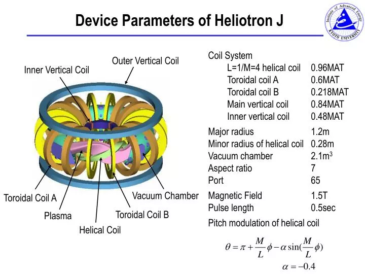
Outer Vertical Coil Inner Vertical Coil Vacuum Chamber Toroidal Coil A Toroidal Coil B Plasma Helical Coil Device Parameters of Heliotron J Coil System L=1/M=4 helical coil 0.96MAT Toroidal coil A 0.6MAT Toroidal coil B 0.218MAT Main vertical coil 0.84MAT Inner vertical coil 0.48MAT Major radius 1.2m Minor radius of helical coil 0.28m Vacuum chamber 2.1m3 Aspect ratio 7 Port 65 Magnetic Field 1.5T Pulse length 0.5sec Pitch modulation of helical coil
The Heliotron J Device TFC-A TFC-B HFC Aux.VFC Main VFC
Heliotron-J surfaces: cfg “A” - helical divertor Configuration “A” is designed to create a helical divertor region shown in red and yellow. The position of the plasma is shown relative to the helical conductor and the vacuum vessel Other configurations • island divertor • standard from T. Mizuuchi, M. Nakasuga et al. Stellararor Workshop 1999
(a) (b) Fig.3 The magnetic surfaces at = 67.5 in the standard configuration. (a) Theexperimental results (corrected) and (b) The calculated magnetic surfaces. Magnetic Surface Mapping STD config, 0.03 Tesla, corrected for earth’s field
Fig. 2 Dependence of the diamagnetic stored energy on the magnetic field strength. Electron Cyclotron Heating • ECH 400kW 53GHZ 50ms • <> ~ 0.2%, <20% radiated • some Fe Ti C O impuritiesPlans: • will upgrade to 70GHz, 500kW • ultimately 4MW ~20kJ? • impurity control • explore bumpiness and hel. divertors W-Diamagnetic vs B is peaked, 700J max