Download
1 / 44
440 likes | 570 Views
Compton Status Report. Tsunehiko OMORI (KEK). e+ source meeting @ANL 17/Sep/2007. World-wide PosiPol Collaboration. Collaborating Institutes: BINP, CERN, DESY, Hiroshima, IHEP, IPN, KEK, Kyoto, LAL, NIRS, NSC-KIPT, SHI, Waseda, BNL, JAEA and ANL.

E N D
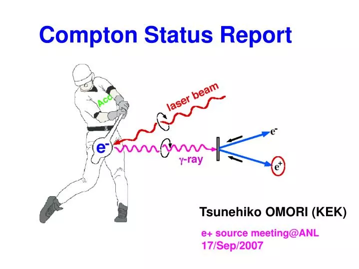
Compton Status Report Tsunehiko OMORI (KEK) e+ source meeting@ANL 17/Sep/2007
World-wide PosiPol Collaboration Collaborating Institutes: BINP, CERN, DESY, Hiroshima, IHEP, IPN, KEK, Kyoto, LAL, NIRS, NSC-KIPT, SHI, Waseda, BNL, JAEA and ANL Sakae Araki, Yasuo Higashi, Yousuke Honda, Masao Kuriki, Toshiyuki Okugi, Tsunehiko Omori, Takashi Taniguchi, Nobuhiro Terunuma, Junji Urakawa, Yoshimasa Kurihara, Takuya Kamitani, X. Artru, M. Chevallier, V. Strakhovenko, Eugene Bulyak, Peter Gladkikh, Klaus Meonig, Robert Chehab, Alessandro Variola, Fabian Zomer, Alessandro Vivoli, Richard Cizeron, Frank Zimmermann, Kazuyuki Sakaue, Tachishige Hirose, Masakazu Washio, Noboru Sasao, Hirokazu Yokoyama, Masafumi Fukuda, Koichiro Hirano, Mikio Takano, Tohru Takahashi, Hirotaka Shimizu, Shuhei Miyoshi, Akira Tsunemi, Ryoichi Hajima, Li XaioPing,Pei Guoxi,Jie Gao, V. Yakinenko, Igo Pogorelsky, Wai Gai, and Wanming Liu POSIPOL 2007 LAL-Orsay, France 23-25 May POSIPOL 2006 CERN April 2006 http://posipol2006.web.cern.ch/Posipol2006/ http://events.lal.in2p3.fr/conferences/Posipol07/
Two ways to get pol. e+ (1) Helical Undurator e- beam E >150 GeV Undulator L > 200 m (2) Laser Compton
Two ways to get pol. e+ (1) Helical Undurator e- beam E >150 GeV Undulator L > 200 m Our Proposal (2) Laser Compton
Why Laser Compton ? i) Positron Polarization. ii) Independence Undulator-base e+ : use e- main linac Problem on design, construction, commissioning, maintenance, Laser-base e+ : independent Easier construction, operation, commissioning, maintenance iii) Polarization flip @ 5Hz iv) High polarization v) Low energy operation Undulator-base e+ : need deccelation Laser-base e+ : no problem
Status of Compton scheme Proof-of-Principle demonstration was done. ATF-Compton Collaboration Polarized -ray generation: M. Fukuda et al., PRL 91(2003)164801 Polarized e+ generation: T. Omori et al., PRL 96 (2006) 114801 We still need many R/Ds and simulations. We have 3 schemes.
Laser Compton e+ Source for ILC We have 3 schemes. 1. Linac Base Laser Compton Linac + External non-stacking Laser Cavity, and No stacking in DR T. Omori et al., Nucl. Instr. and Meth. in Phys. Res., A500 (2003) pp 232-252 Proposal by V. Yakimenko and I. Pogorersky 2. Ring Base Laser Compton Storage Ring + Laser Stacking Cavity, and moderate stacking in DR (~100 times) S. Araki et al., physics/0509016 3. ERL Base Laser Compton ERL + Laser Stacking Cavity, and many stacking in DR (~1000 times) Good! But we have to choose!
to e+ conv. target 4GeV 1A e- beam 30MeV beam 15MeV e+ beam ~2 m Linac Scheme • Polarized γ-ray beam is generated in the Compton back scattering inside optical cavity of CO2 laser beam and 4 GeV e-beam produced by linac. • 4GeV 15nC e- beam with 12 ns spacing. • 10 CPs, which stores 10 J CO2 laser pulse repeated by 83 Mhz cycle. • 5E+11 γ-ray -> 2E+10 e+ (2% conversion) • 1.2μs pulse, which contains 100 bunches, are repeated by 150 Hz to generated 3000 bunches within 200ms. • No stacking in DR By V. Yakimenko and Pogorersky
Compton scattering of e- beam stored in storage ring off laser stored in Optical Cavity. 15 nC 1.3 GeV electron bunches x 10 of 600mJ stored laser -> 1.7E+10 γ rays -> 2.4E+8 e+. By stacking 100 bunches on a same bucket in DR, 2.4E+10 e+/bunch is obtained. Compton Ring Scheme
CLIC Scheme Compton configuration for polarized e+ 2.424 GeV 360 m e+ DR 2.424 GeV 450 turns makes 311 bunches with 4.5x10⁹ e+/bunch e+ PDR and Accumulator ring C = 68 m, 226 ns/turn, 311 bunches with 6.2x10¹⁰ e-/bunch Injector Linac 2.2 GeV 1.5 GHz RF gun Drive Linac 1.3 GeV 1.5 GHz 3 GHz 50 Hz Compton ring Pre-injector Linac for e+ 200 MeV g g (23-29 MeV)6.9x10⁸ /turn/bunch Stacking cavity 9.8x10⁶ pol. e+/turn/bunch by F. Zimmermann & Louis e+ target 1 YAG Laser pulse
Both advantages (high yield + high repetition) are compatible in ERL solution. 0.64 nC 1.3 GeV bunches x 10 of 600 mJ laser, repeated by 40.8MHz -> 6.4E+9 γ-rays -> 2E+7 e+. Continuous stacking the e+ bunches on a same bucket in DR during 100ms, the final intensity is 2E+10 e+. ERL scheme = Linac scheme + Ring scheme 125m SC Linac (15MV/m) 24 mA 10 of 600mJ Optical Cavities
R&D items CR/ERL simulations studies (Kharkov, LAL, JAEA, KEK) design studies beam dynamics studies Optical Cavity (LAL, Hiroshima, KEK) experimental R/D e+ capture (LAL, ANL) We will start collaboration with KEKB upgrade study e+ stacking in DR (CERN) Basic beam dynamics studies Laser Fiber laser / Mode-lock laser (cooperation with companies) CO2 laser (BNL)
CO2 oscillator 200ps 150ns Ge 1mJ 5ps 10mJ 5ps from YAG laser PC PC TFP 10mJ 5ps 300mJ 5 ps 2x30mJ 1J IP#1 IP#5 e- CO2 Laser system for ILC Kerr generator intra-cavity pulse circulation : • pulse length 5 ps • energy per pulse 1 J • period inside pulse train 12 ns • total train duration 1.2 s • pulses/train 100 • train repetition rate 150 Hz • Cumulative rep. rate 15 kHz • Cumulative average power 15 kW See Yakimenko's talk tomorrow
Test setup Observations: • Optical gain over 4 ms • Single seed pulse amplification continues to the end See Yakimenko's talk tomorrow 3% over 1 ms
325 MHz 325 MHz Laser Pulse Stacking Cavity Laser-electron small crossing angle Laser bunches Lcav = n Lcav = m Llaser Cavity Enhancement Factor = 1000 - 105 See Omori's talk tomorrow
Prototype Cavities 2-mirror cavity (Hiroshima/KEK) 4-mirror cavity (LAL) high enhancement very small spot size complicated control moderate enhancement small spot size simple control See Omori's talk tomorrow
D CP target Capture simulation for ERL Compton Preliminary study by Wanming & Wei (ANL) target: tungsten 0.4 X0 D = 50m D = 20m if Pz > 18 MeV/c --> Pol ~ 80% Ne+/N ~ 0.3% (geo) at target exit ~ 100 cm-mrad (D=50m) ~ 50 cm-mrad (D=20m)
Design Study of 10 collision points in ERL Number of gamma-rays (relative) simulated using CAIN by T. Omori with help of K.Yokoya s = 40 m s = 0 m -rays e-beam e-beam Target 3.9 m D = 40 m Laser pulse stacking Cavity Focusing optics (triplet) Ng = 1 0.93 0.84 0.72 0.64 0.55 0.49 0.49 0.47 0.43 Ng sum of 10 Collision Points = 6.5(10 was expected in naive assumption)
Design Study of 10 collision points in ERL by K. Yokoya
Design Study of 10 collision points in ERL Optics of Beamline total for dP = -2% calculated by K. Yokoya
1. Laser-Compton has a large potential as a future technology. 2. Many common efforts can be shared in a context ofvarious applications. – Compact and good quarity X-ray source for industrial and medical applications – -ray source for disposal of nuclear wastes – Beam diagnostics with Laser – Polarized Positron Generation for ILC and CLIC – collider 3. State-of-the-art technologies are quickly evolved with world-wide synergy. – Optical Cavity, – Laser, – ERL .......... PosiPol-Collaboration
1. Laser Compton ILC e+ source is an attractive alternative Independent system high polarization 5 Hz polarization flip Operability wide applications Summary
1. Laser Compton ILC e+ source is an attractive alternative Independent system high polarization 5 Hz polarization flip Operability wide applications Summary • 2. Several solutions are proposed • Linac Laser Compton • Ring Laser Compton • ERL Laser Compton
1. Laser Compton ILC e+ source is an attractive alternative Independent system high polarization 5 Hz polarization flip Operability wide applications Summary • 2. Several solutions are proposed • Linac Laser Compton • Ring Laser Compton • ERL Laser Compton 3. We have a world-wide collaboration for Compton. Many studies are on going (see tomorrows's talks) Not only for ILC e+ source. Also for many other applications.
1. Laser Compton ILC e+ source is an attractive alternative Independent system high polarization 5 Hz polarization flip Operability wide applications Summary • 2. Several solutions are proposed • Linac Laser Compton • Ring Laser Compton • ERL Laser Compton 3. We have a world-wide collaboration for Compton. Many studies are on going (see tomorrows's talks) Not only for ILC e+ source. Also for many other applications. 4. Compton-Undulator collaboration in ILC e+ source: capture section in Attracting many researchers: X-ray source (for example)
Capture and Transmission 1 ξ Energy (MeV) By. A. Vivoli Bunch Compressor AMD Target Pre-accelerator To the accelerator From Compton Cavities e- γ e+ Bending Magnets Solenoid Cavities Magnetic field Electric field
Recoiled Spectra By E. Bulyak (Kharkov)
KEK-ATF and LAL advance experiments with external cavity to stack laser beam. Goal is to achieve high enhancement & small laser spot size. LAL cavity has theoretically high enhancement, but needs more complicated control. KEK cavity has less enhancement, but its control is simpler. Optical Cavity R&Ds
What we want ILC YAG laser case What we will at KEK-ATF What we did (Takezawa, 2004) Electron Energy (GeV) 1.3 1.3 1.3 Ne/bunch 6.2E10 2.0E10 1.0E10 Electron repetition rate (MHz) 325 357 357 Hor. Beam size (rms,us) 25 79 79 Ver. Beam size (rms,us) 5 6 6 Bunch length (rms,mm) 5 9 9 Laser type (wavelength) YAG(1064nm) YAG(1064nm) YAG(1064nm) Laser frequency (MHz) 325 357 357 Laser radius (rms, um) 5 29 125 Laser pulse width (rms,mm) 0.9 0.9 0.9 Laser pulse power /cavity 750uJ x 1000 28nJ(10W) x 1000 1nJ(0.3W) x 65 Number of laser cavities 30 1 1 Crossing angle (degree) 8 10 90 Optical Cavity History at KEK-ATF By H. Shimizu
Double clad-core optical fiber. InGaAs LD (940nm) is for pumping. Typical core size is 6 – 40 m. Yb Fibre Laser J. Limpert,T. Schreiber, and A. Tünnermann, “Fiber based high power laser systems" By M. Hanna
World-Wide-Web of Laser Compton 4th Generation light source ERL/Ring ILC e+ CLIC e+ e+ source Laser Compton SuperB Material Science γγ collider LW monitor/ Polarimetry Medical applications X-ray source Optical Cavity Industrial applications e- source ILC, ERL High power laser
1. Laser-Compton has a large potential as a future technology. 2. Many common efforts can be shared in a context ofvarious applications. – Compact X-ray source for industrial and medical applications – -ray source for disposal of nuclear wastes – Beam diagnostics with Laser – Polarized Positron Generation for ILC and CLIC – collider 3. State-of-the-art technologies are quickly evolved with world-wide synergy. – Optical Cavity, – Laser, – ERL .......... PosiPol-Collaboration
Provide more realistic gamma data --> 10 collision points s = 40 m s = 0 m -rays e-beam e-beam Target 3.9 m D = 40 m Laser pulse stacking Cavity Focusing optics (triplet)
Table of the beam parameters. Electron beam Ne/bunch = 1x10^{10} beta_horizontal = 0.16 m beta_vertical = 0.16 m emittance_horizontal = 6.25x10^{-10} emittance_vertical = 6.25x10^{-10} sigma_horizontal = 10 micron (in the first collision point) sigma_vertical = 10 micron (in the first collision point) sigma_longitudinal = 0.2 mm Laser beam (for each collision point) Energy in a pulse = 0.6 J sigma_rateral = 5 micron sigma_longitudinal = 0.24 mm
Gamma Data Data was sent to Wanming-san (ANL) Data will be sent to Vivoli-san (LAL)
Capture Section (+ B.C.) Adiabatic Matching Device Bunch Compressor Pre-accelerator Target From Compton Cavities e- To the accelerator g g e+ Bending Magnets Drifts Solenoid Cavities Magnetic field Electric field A. VIVOLI*, B. MOUTON, A. VARIOLA, O. DADOUN (LAL/IN2P3-CNRS), R. CHEHAB (IPNL &LAL/IN2P3-CNRS), Orsay, France
Pre-accelerator Solenoid • Magnetic Field = 0.5 T • Length = ~ 31 m Accelerating Cavities: • Length = 1.25 m • Aperture = 2.3 cm • Average accelerating Field = ~ 7 MV/m • Number of cavities = 22 Drift length between cavities = 13 cm A. VIVOLI*, B. MOUTON, A. VARIOLA, O. DADOUN (LAL/IN2P3-CNRS), R. CHEHAB (IPNL &LAL/IN2P3-CNRS), Orsay, France
World-Wide-Web of Laser Compton 4th Generation light source ERL/Ring ILC e+ CLIC e+ e+ source Laser Compton SuperB Material Science γγ collider LW monitor/ Polarimetry -ray source Nuclear wasit Optical Cavity X-ray source Medical applications Industrial applications e- source ILC, ERL High power laser