Download
1 / 1
10 likes | 64 Views
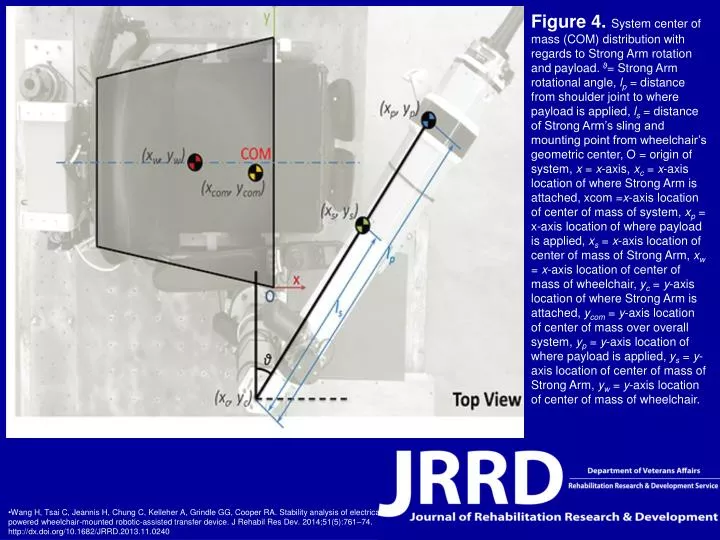
Explore system center of mass distribution with regards to Strong Arm rotation and payload application. Study Strong Arm's rotational angle, distances lp and ls, axis locations, and more to ensure stability. Read the research for a detailed analysis.

E N D
Figure 4. System center of mass (COM) distribution with regards to Strong Arm rotation and payload. ϑ= Strong Arm rotational angle, lp = distance from shoulder joint to where payload is applied, ls = distance of Strong Arm’s sling and mounting point from wheelchair’s geometric center, O = origin of system, x = x-axis, xc = x-axis location of where Strong Arm is attached, xcom =x-axis location of center of mass of system, xp = x-axis location of where payload is applied, xs = x-axis location of center of mass of Strong Arm, xw = x-axis location of center of mass of wheelchair, yc = y-axis location of where Strong Arm is attached, ycom = y-axis location of center of mass over overall system, yp = y-axis location of where payload is applied, ys = y-axis location of center of mass of Strong Arm, yw = y-axis location of center of mass of wheelchair. • Wang H, Tsai C, Jeannis H, Chung C, Kelleher A, Grindle GG, Cooper RA. Stability analysis of electrical powered wheelchair-mounted robotic-assisted transfer device. J Rehabil Res Dev. 2014;51(5):761–74.http://dx.doi.org/10.1682/JRRD.2013.11.0240