Download

1 / 25
250 likes | 455 Views
Federal Aviation Administration. Composite and Aluminum Wing Tank Flammability Comparison Testing. International Aircraft Systems Fire Protection Working Group Koeln, Germany May 19-20, 2009. Steve Summer

E N D
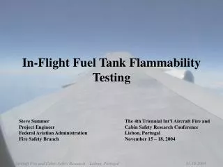
Federal Aviation Administration Composite and Aluminum Wing Tank Flammability Comparison Testing International Aircraft Systems Fire Protection Working GroupKoeln, Germany May 19-20, 2009 Steve Summer William Cavage Federal Aviation AdministrationFire Safety Branch
Outline • Overview • Enironmental Chamber Testing • Airflow Induction Facility Testing • Panel Heat Tests • Planned Work
Overview - Background • FAA has released a final rule requiring the reduction of flammability within high risk fuel tanks, with the benchmark being a traditional unheated aluminum wing tank • Next generation aircraft scheduled to enter service in the coming years have composite skin that could change baseline fleet wing tank flammability • Logic assumes composite wings will be more flammable as they reject heat less effectively compared to aluminum • Could also absorb more heat and/or transfer heat more readily to the ullage
Overview: Wing Tank Flammability Parameters Flammability Drivers on Ground • Top skin and ullage are heated from sun • Hot ullage heats top layer of fuel, causing evaporation of liquid fuel • Bulk fuel temperature however, remains relatively low Flammability Drivers In Flight • Decreasing pressure causes further evaporation of fuel • Cold air flowing over the tank causes rapid cooling and condensation of fuel vapor in ullage • These concepts were observed during previous testing and reported on recently (see rpt #DOT/FAA/AR-08/8) • The objective is to now compare flammability progression in a wing fuel tank test article with both aluminum skin and composite skin
Test Apparatus - Wing Tank Test Article • Constructed wing tank test article from previous test article • Interchangeable aluminum and composite skin panels on top and bottom with an aerodynamic nose and tail piece • Tank is vented and has a gas sample port for THC analysis, pressure transducer, and an extensive array of thermocouples • Radiant panel heaters used to heat top surface to simulate ground conditions
Test Apparatus - Environmental Chamber Testing • Utilized recently made wing fuel tank test article in altitude chamber to compare Al and Composite Flammability • Performed two identical tests, one with each skin, with 90 deg F ambient temperature, moderate top heat, and average F.P. fuel • Measured skin, ullage and fuel temperature progressions over 5-hour period
Results - Scale Tank in Altitude Chamber • Testing shows large increases in flammability with composite wing fuel tank skin not seen with aluminum skin when heated from top during ground conditions • Used same heat source, fuel flashpoint, and ambient temperature on tank with both skin surfaces • When bringing the fuel tank to altitude and dropping the temperature, spike in flammability occurred for both • This is not representative of a wing fuel tank ullage because flight conditions not simulated • Altitude conditions not simulated with good fidelity (differing altitude profiles)
Test Apparatus – Airflow Induction Test Facility • Subsonic induction type, nonreturn design wind tunnel • Induction drive powered by two Pratt & Whitney J-57 engines
Test Apparatus – Airflow Induction Test Facility • Test article was mounted in the high speed test section • 5-½ foot in diameter and 16 feet in length. • Maximum airspeed of approximately 0.9 mach, though with the test article we measured airspeeds of approximately 0.5
Test Apparatus – Airflow Induction Test Facility • Due to the design, a simulated altitude (i.e. reduction in pressure) is observed as the airspeed is increased.
Test Conditions – Airflow Induction Test Facility • Fuel levels of 40, 60, 80% were examined • Radiant heaters used to heat top surface of tank for 1 hour prior to fueling • Tests conducted with two different heat settings • Fuel was preconditioned to 90F and transferred into the tank • Heating of tank was continued for 1 hour at which point heaters were removed and wind tunnel was started. • Engines initially run at idle for 5-10 minute warm up period and then taken to 90% throttle • 90% throttle position maintained for a period of 30 minutes • Discrete THC sample points were taken throughout testing
Results – Airflow Induction Facility Tests • Similar to Environmental Chamber tests, significant increases in both ullage temperature and flammability are observed with composite as compared with aluminum skin • This correlation is evidence that ullage temperature is driver of flammability • Fuel temperature increase is also observed, but not as severe • When aluminum tank is heated sufficiently, and the starting temperature and flammability values are equivalent, the two tanks behave in a very similar manner.
Test Apparatus – Panel Heat Tests • Examined the static heating/cooling aspects of each material with support of the FAA Video Lab • 3-ft x 3-ft panel of each material suspended and heated from above with 3 radiant panel heaters • Panels were subjected to radiant heat for 20 minutes, followed by cooling of approximately 30 minutes • Single thermocouple placed in center of panel, utilized as a reference point • FLIR camera utilized to examine the panels’ heat signature throughout test
Aluminum Panel – FLIR Camera Results 10 minutes 0 minutes 20 minutes
Aluminum Panel – FLIR Camera Results (cont.) 40 minutes 30 minutes 50 minutes
Composite Panel – FLIR Camera Results 10 minutes 0 minutes 20 minutes
Composite Panel – FLIR Camera Results (cont.) 40 minutes 30 minutes 50 minutes
Planned Work • Examine the effects of different colored topcoats on the heat rejection of composite and aluminum panels • Examine the effects of varying thickness of composite panels • 727 wing surge tank utilized in previous testing will be re-skinned with composite material for further testing this summer