Download
1 / 48
490 likes | 624 Views
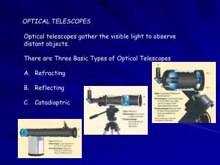
Instrumentation Concepts Ground-based Optical Telescopes. Keith Taylor (IAG/USP) Aug-Nov, 2008. IAG-USP (Keith Taylor). Aug-Sep, 2008. Introduction. Adaptive Optics. Why is adaptive optics needed?. Turbulence in earth’s atmosphere makes stars twinkle

E N D
IAG/USP (Keith Taylor) Instrumentation ConceptsGround-based Optical Telescopes Keith Taylor (IAG/USP) Aug-Nov, 2008 IAG-USP (Keith Taylor) Aug-Sep, 2008
Introduction Adaptive Optics IAG/USP (Keith Taylor)
Why is adaptive optics needed? Turbulence in earth’s atmosphere makes stars twinkle More importantly, turbulence spreads out light; makes it a blob rather than a point Even the largest ground-based astronomical telescopes have no better resolution than an 20cm telescope!
Speckles (each is at diffraction limit of telescope) Images of a bright star, Arcturus 1 m telescope ~ 1 arc sec ~ / D Long exposure image Short exposure image Image with adaptive optics
Turbulence changes rapidly with time Image is spread out into speckles Centroid jumps around (image motion) “Speckle images”: sequence of short snapshots of a star, using an infra-red camera
tropopause 10-12 km wind flow over dome boundary layer ~ 1 km Heat sources within dome Turbulence arises in many places stratosphere
Atmospheric perturbations cause distorted wavefronts Rays not parallel Index of refraction variations Plane Wave Distorted Wavefront
blur Optical consequences of turbulence • Temperature fluctuations in small patches of air cause changes in index of refraction (like many little lenses) • Light rays are refracted many times (by small amounts) • When they reach telescope they are no longer parallel • Hence rays can’t be focused to a point: Point focus Light rays affected by turbulence Parallel light rays
Imaging through a perfect telescope With no turbulence, FWHM is diffraction limit of telescope, ~/D Example: /D = 0.05 arcsec for = 1m ; D = 4m With turbulence, image size gets much larger (typically 0.5 - 2 arcsec) FWHM ~/D 1.22 /D in units of /D Point Spread Function (PSF): intensity profile from point source
Wavefront of light r0 “Fried’s parameter” Characterize turbulence strength by quantity r0 • “Coherence Length” r0 : distance over which optical phase distortion has mean square value of 1 rad2 (r0 ~ 15 - 30cm at good observing sites) • Easy to remember: r0 = 10 cm FWHM = 1 arcsec at = 0.5m Primary mirror of telescope
Effect of turbulence on image size • If telescope diameter D >> r0 , image size of a point source is /r0 >> /D • r0 is diameter of the circular pupil for which the diffraction limited image and the seeing limited image have the same angular resolution. • r0 25cm at a good site. So any telescope larger than this has no better spatial resolution! / D “seeing disk” / r0
How does adaptive optics help?(cartoon approximation) Measure details of blurring from “guide star” near the object you want to observe Calculate (on a computer) the shape to apply to deformable mirror to correct blurring Light from both guide star and astronomical object is reflected from deformable mirror; distortions are removed
Adaptive optics increases peak intensity of a point source No AO With AO Intensity With AO No AO
Definition of “Strehl”: Ratio of peak intensity to that of “perfect” optical system Intensity x AO produces point spread functions with a “core” and “halo” • When AO system performs well, more energy in core • When AO system is stressed (poor seeing), halo contains larger fraction of energy (diameter ~ r0) • Ratio between core and halo varies during night
Schematic of adaptive optics system Feedback loop: next cycle corrects the (small) errors of the last cycle
How to measure turbulent distortions (one method among many) Shack-Hartmann wavefront sensor
Shack-Hartmann wavefront sensor measures local “tilt” of wavefront • Divide pupil into subapertures of size ~ r0 • Number of subapertures (D/r0)2 • Lenslet in each subaperture focuses incoming light to a spot on the wavefront sensor’s CCD detector • Deviation of spot position from a perfectly square grid measures shape of incoming wavefront • Wavefront reconstructor computer uses positions of spots to calculate voltages to send to deformable mirror
IAG/USP (Keith Taylor) Aberrations in the Eye … and on the telescope
How a deformable mirror works (idealization) BEFORE AFTER Deformable Mirror Incoming Wave with Aberration Corrected Wavefront
Real deformable mirrors have smooth surfaces • In practice, a small deformable mirror with a thin bendable face sheet is used • Placed after the main telescope mirror
Most deformable mirrors today have thin glass face-sheets Glass face-sheet Light Cables leading to mirror’s power supply (where voltage is applied) PZT or PMN actuators: get longer and shorter as voltage is changed (PMN = Lead Magnesium Niobate – Electrostrictive) Anti-reflection coating
Deformable mirrors come in many sizes • Range from 13 to > 900 actuators (degrees of freedom) ~300mm Xinetics ~50mm
New developments: tiny deformable mirrors • Potential for less cost per degree of freedom • Liquid crystal devices • Voltage applied to back of each pixel changes index of refraction locally (not ready for prime time yet) • MEMS devices (micro-electro-mechanical systems) - very promising today Electrostatically actuated mirror diaphragm post Continuous mirror
If there’s no close-by “real” star, create one with a laser • Use a laser beam to create artificial “star” at altitude of 100 km in atmosphere
Laser guide stars are operating at Lick, Keck, Gemini North, VLT Observatories Keck Observatory Lick Observatory
Galactic Center with Keck laser guide star Keck laser guide star AO Best natural guide star AO
Summit of Mauna Kea volcano in Hawaii Subaru 2 Kecks Gemini North
Astronomical observatories with AO on 6 - 10 m telescopes • Keck Observatory, Hawaii • 2 telescopes • European Southern Observatory (Chile) • 4 telescopes • Gemini North Telescope, Hawaii • Subaru Telescope, Hawaii • MMT Telescope, Arizona • Soon: • Gemini South Telescope, Chile • Large Binocular Telescope, Arizona
Adaptive optics system is usually behind the main telescope mirror • Example: AO system at Lick Observatory’s 3 m telescope Support for main telescope mirror Adaptive optics package below main mirror
Lick adaptive optics system at 3m Shane Telescope DM Off-axis parabola mirror IRCAL infra-red camera Wavefront sensor
Palomar adaptive optics system AO system is in Cassegrain cage 200” Hale telescope
Adaptive optics makes it possible to find faint companions around bright stars Two images from Palomar of a brown dwarf companion to GL 105 200” telescope With AO No AO Credit: David Golimowski
The Keck Telescopes Adaptive optics lives here
Person! Keck Telescope’s primary mirror consists of 36 hexagonal segments Nasmyth platform
Neptune in infra-red light (1.65m) With Keck adaptive optics Without adaptive optics 2.3 arc sec May 24, 1999 June 27, 1999
Neptune at 1.6 m: Keck AO exceeds resolution of Hubble Space Telescope HST - NICMOS Keck AO ~2 arc sec 2.4 meter telescope 10 meter telescope (Two different dates and times)
Uranus with Hubble Space Telescope and Keck AO L. Sromovsky Keck AO, IR HST, Visible Lesson: Keck in near IR has ~ same resolution as Hubble in visible
Uranus with Hubble Space Telescope and Keck AO de Pater HST, Visible Keck AO, IR Lesson: Keck in near IR has ~ same resolution as Hubble in visible
Some frontiers of astronomical adaptive optics • Current systems (natural and laser guide stars): • How can we measure the Point Spread Function while we observe? • How accurate can we make our photometry? astrometry? • What methods will allow us to do high-precision spectroscopy? • Future systems: • Can we push new AO systems to achieve very high contrast ratios, to detect planets around nearby stars? • How can we achieve a wider AO field of view? • How can we do AO for visible light (replace Hubble on the ground)? • How can we do laser guide star AO on future 30-m telescopes?
Frontiers in AO technology • New kinds of deformable mirrors with > 5000 degrees of freedom • Wavefront sensors that can deal with this many degrees of freedom • Innovative control algorithms • “Tomographic wavefront reconstuction” using multiple laser guide stars • New approaches to doing visible-light AO
Ground-based AO applications • Biology • Imaging the living human retina • Improving performance of microscopy (e.g. of cells) • Free-space laser communications (thru air) • Imaging and remote sensing (thru air)
Why is adaptive optics needed for imaging the living human retina? • Around edges of lens and cornea, imperfections cause distortion • In bright light, pupil is much smaller than size of lens, so distortions don’t matter much • But when pupil is large, incoming light passes through the distorted regions • Results: Poorer night vision (flares, halos around streetlights). Can’t image the retina very clearly (for medical applications) Edge of lens Pupil
Adaptive optics provides highest resolution images of living human retina Austin Roorda, UC Berkeley With AO: Resolve individual cones (retina cells that detect color) Without AO
Horizontal path applications • Horizontal path thru air: r0 is tiny! • 1 km propagation distance, typical daytime turbulence: r0 can easily be only 1 or 2 cm • So-called “strong turbulence” regime • Turbulence produces “scintillation” (intensity variations) in addition to phase variations • Isoplanatic angle also very small • Angle over which turbulence correction is valid • 0 ~ r0 / L ~ (1 cm / 1 km) ~ 2 arc seconds (10 rad)
AO Applied to Free-Space Laser Communications • 10’s to 100’s of gigabits/sec • Example: AOptix • Applications: flexibility, mobility • HDTV broadcasting of sports events • Military tactical communications • Between ships, on land, land to air