Download
1 / 27
270 likes | 441 Views
Advances in Polarized Electron Sources for High-Energy Accelerators. Jym Clendenin CharlieFest SLAC, January 27, 2006. Contents of talk. SLC era Progress since SLC R&D plans for ILC. Polarized electron sources for high-energy accelerators must provide:. High polarization

E N D
Advances in Polarized Electron Sources for High-Energy Accelerators Jym Clendenin CharlieFest SLAC, January 27, 2006
Contents of talk • SLC era • Progress since SLC • R&D plans for ILC
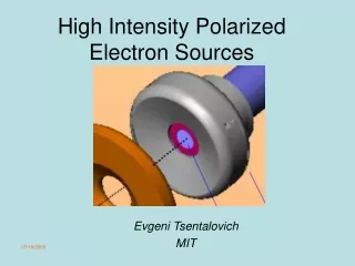
Polarized electron sources for high-energy accelerators must provide: • High polarization • High peak current • Operational simplicity and stability • Nearly zero downtime
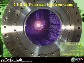
3 elements to a GaAs-type source • Vacuum structure (i.e., electron gun) • Photocathode • Laser system
Photoemission from p-type semiconductors F for GaAs a few eV, reduced to ~1 eV with Cs,O Bands bend down with p doping, ~0.75 eV for GaAs Net result: Vacuum level below CBM in bulk (negative electron affinity) Spicer’s 3-step model
Polarization for bulk GaAs Energy vs Momentum Symmetry at G Polarization vs excitation photon energy Spin-orbit split-off band below VBM by DSO=0.35 eV Pmax = (3-1)/(3+1)=0.5
Surface Charge Limit Cannot increase charge in a single pulse by simply increas- ing the laser energy!
The first SLC run with polarized e- Re-cesiated (C) when QE not sufficient to maintain required charge (~81010 e-) Re-activated (A) when re-cesiation cycles became too short P~25%, source availability ~90%
Gun improvementsbegun in ’92 • Load lock • Channel cesiators • Nanoammeters • Low field electrodes • Larger diameter GaAs cathodes • Lower cathode temperature
Load lock attached to rear of gun with top of corona shield removed
Single-layer Strained GaAsP/GaAs Bi-axial compressive strain lifts the degeneracy of the hh and lh bands at G da~1% yields d of 50-80 meV
SLC 1993-1998 • P~80% using GaAsP/GaAs cathode • I at source ~8x10¹⁰ e- for each of the 2 micropulses • With LL, no need to re-activate • Availability >97% • Operated entirely by MCC staff except for YAG flashlamp changes every few weeks
Parameter SLC NLC ILC at Source Design NC-SB SC-LB ne nC 20 2.4 6.4 Dz ns 3 0.5 2 Impulse, avg A 6.7 4.8 3.2 Impulse, peak A 11 (SCL) Toward the next collider Charge requirements at source NLC/ILC peak current < SLC, but total charge per macropulse much higher NLC: 2.9x10¹² e- in 270 ns ILC: 1.1x10¹⁴ e- in 0.94 ms
Uniformly doped, unstrained, 100-nm GaAs cathodes. QE=0.45, 0.9, 0.4, 0.4% in order of increasing dopant density. Laser energy increases in equal steps to 150 W/cm2. SCL not visible for dopant concentration ≥21019 cm-3
GaAs0.64P0.36/GaAs SL with5-nmGaAs final layer doped to 51019 cm-3 Peak current exceeds that required for the NLC micropulse Same flashlamp-pumped Ti:sapphire laser as for E-158 (75 ns) (250 ns)
QE performance of SVT-4249 (E158-III cathode) after ~1 year
QE profile for SVT-4249 August 21, 2003 June 28, 2005
CTS Measurements QE at Pe max: 1.2% 0.3% Pe max CTS/Møller): 86(90)% 81(85)% GaAs0.64P0.36/GaAs SL (4+4 nm x 12) grown by SVT using MBE GaAs0.66P0.34/GaAs0.95P0.05single strained-layer 90-nm grown by SVT using MBE
ILC R&D Plans • Photocathodes for higher polarization and/or QE: AlInGaAs/AlGaAs SL high-strain or low CB offset; AlInGaAs/GaAsP SL strain-compensated; grided cathodes; GaN based cathodes for robustness • Higher voltage gun: new materials for DC gun; prototype RF gun • Lasers: generate ILC macropulse in visible
Workshop on Polarized Electron Sources, Mainz, Germany, Oct., 2004