Download
1 / 12
130 likes | 313 Views
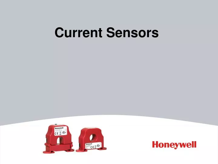
Current Sensors. Introduction. Honeywell is proud to introduce its new line of current sensors and switches. Current sensors and switches detect whether current is flowing through electrical equipment, such as pumps and motors. Detects when equipment is turned on or off.

E N D
Introduction • Honeywell is proud to introduce its new line of current sensors and switches. • Current sensors and switches detect whether current is flowing through electrical equipment, such as pumps and motors. • Detects when equipment is turned on or off. • Transmits the status to a building management system, DDC or PLC controller. • The wires are threaded through a hole in the current sensor which measures the current going through the wire. • Current sensors and transmitters can be used to detect a motor failure, belt loss or slippage, or a mechanical failure.
Key Features • Higher operating range (250A) and very low trip points- down to 0.12 Amps • Integral DIN rail mount • Solid core and split core models • Quick signal allows for service actions to be taken immediately to prevent damage and reduce downtime • Current sensors are rated at 250 amps, allowing you to meet high-amp situations without needing transformer • UL rated • 5-year warranty
Key Features TRANSMITTER Jumper Selectable Current Range SWITCH Solid core Split core UL rated DIN Rail integrally mounted
Installation • Easy to install and service • Built-in DIN rail mounting flange simplifies installation • Red and green LEDs – on adjustable switches. Red indicates over the trip point, green indicates below.
Current Switches • CSS solid and CSP split core fixed and adjustable trip points • Monitor fans, pumps, motors, compressors, or other electrical equipment. • Change in current can trip the sensor to indicate equipment status or alarm condition. • Up to 250 Amps. • Do not need to be externally powered, since the power for the • switch is induced from the conductor being monitored. • Red LED – Indicates above the trip point on fixed models. • Red and Green Status LEDs – indicate above or below trip point on adjustable models.
Current Sensors (Transmitters) • CTS solid and CTP split core 4-20mA, 0-5 and 0-10Vdc • Solid core excellent choice for new installations • Split core ideal for retrofit or existing installations • Linear proportional output signal, can be monitored by your Building Management, DDC or PLC controller. • Available in either an Average or True RMS (for VFDs) output version. • Jumper selectable input ranges except for the 0 to 5 Amp input range. • Current sensors can be used in load trending (current monitoring) type applications. • Sensors are fast acting, reliable and extremely easy to install. • No additional DIN rail mounting clips are necessary, due to the unique design of the integral din rail mounting flange. • All of the CTS20 and CTP20 series current sensors are factory calibrated using a NIST Traceable standard • The CTS20 and CTP20 must be externally powered using a 12 to 35 Vdc power supply.