Download
1 / 43
440 likes | 744 Views
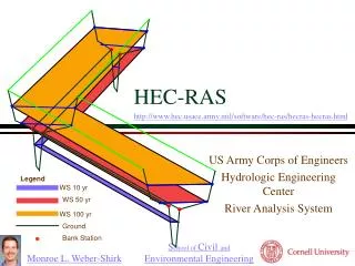
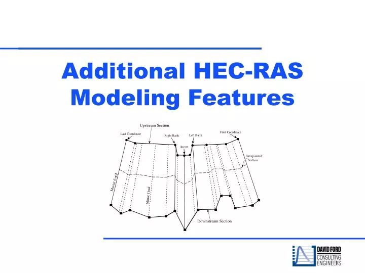
Additional HEC-RAS Modeling Features. Objective. To allow you to become familiar with some of the optional capabilities in HEC-RAS. Optional Capabilities. Multiple Plan Analysis Effective Area Option Cross Section Interpolation Graphical Editing Features Mixed Flow Regime Calculations

E N D
Objective • To allow you to become familiar with some of the optional capabilities in HEC-RAS
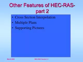
Optional Capabilities • Multiple Plan Analysis • Effective Area Option • Cross Section Interpolation • Graphical Editing Features • Mixed Flow Regime Calculations • Flow Distribution Calculations • Inline Weirs and Gated Spillways
Notes on Plans • Modifications can be made to the geometry and/or flow data, and then saved in separate files. • Plans are formulated by selecting a particular geometry file and a particular flow file. • The multiple plan option is useful when, for example, a comparison of existing conditions and future channel modifications are to be analyzed.
Multiple Plan Option • Can be used to perform a design of a specific geometric feature. • For example, if you are sizing a bridge opening, a separate geometry file could be developed for a base condition (no bridge), and then separate geometry files could be developed for each possible bridge configuration. • A plan would consist of a flow file and one of the geometry files. Computations are performed for each plan individually.
Viewing tables and graphs • Once the computations are performed for all the plans, the user can then view output in a graphical and tabular mode for any single plan or combination of plans.
Ineffective flow areas KE = aV2/2g, where V =Q/A • Velocity head is associated with flow in downstream direction • If area in the cross section is not carrying flow it should not be included • The “ineffective area” option of RAS is used for this
Example:Ineffective Flow Areas at a Bridge Four cross sections are needed to describe the active flow area for flow through the bridge opening
Designation of Ineffective Area Related to Type of Bridge Flow Types of Bridge Flow • Low flow through bridge opening • Pressure flow through bridge opening • Weir flow • Pressure and weir flow • High flows over bridge and approaches
Location of Cross Sections 2 and 3 Bounding sections for bridge Define bridge interior for upstream and downstream bridge sections Must be defined before bridge data are input Usually have ineffective flow area defined Cross Sections at Bridge
Defining Ineffective Area • Permanently block out area • Block out area until water surface reaches a given elevation • Multiple blocks • Use a levee • Use very high n-value in regions with very low velocity
Normal Blocked Obstructions Blocked obstructions decrease flow area and add wetted perimeter when the water comes in contact with the obstruction
Multiple Blocked Obstructions Up to 20 individual blocks can be defined. The left station, right station, and an elevation are entered for each of the blocks.
Left Ineffective Flow Station Right Ineffective Flow Station Ineffective Area Option The area is included in the storage calculations, but it is not included as part of the active flow area. No additional wetted perimeter is added to the active flow area.
Left Levee Station Levee Option No water can go to the left of the left levee station or to the right of the right levee station until the levee elevations are exceeded.
Levee Added A vertical wall is placed up to the established levee height. Additional wetted perimeter is included when water comes into contact with the levee wall. Left Levee Station and Elevation
Cross Section Interpolation May Be Needed When: • The change in velocity head is too large • To better model friction losses • To prevent the program from defaulting to critical depth • To generate a smoother plot of the water surface profile
Cross Section Interpolation • CAUTION: Automatic interpolation should not be used as a replacement for required cross section data! • Interpolation can improve model calculations (especially for unsteady flow analysis)
Mixed Flow Calculations Steady Flow Calculations • Subcritical Flow • Supercritical Flow • Mixed Flow Unsteady Flow Calculations • Subcritical Flow • Supercritical Flow • Mixed Flow
Flow Distribution Option The flow distribution option allows the user to see in different parts of the cross section: • The amount of flow • The flow velocity
CAUTION • Flow distribution varies vertically and horizontally (all flows are 3-D in nature ) • HEC-RAS is a 1-D model • Flow distribution is based on area and wetted perimeter of each flow slice (using fewer slices is generally better)
Sluice and Radial Gates Gate openings can handle both submerged and unsubmerged conditions
Recap We covered: • Multiple Plan Analysis • Effective Area Option • Cross Section Interpolation • Flow Regimes • Flow Distribution Calculations • Inline Weirs and Gated Spillways