Download
1 / 37
370 likes | 502 Views
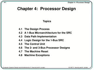
Chapter 1: The General Purpose Machine. Topics 1.1 The General Purpose Machine 1.2 The User’s View 1.3 The Machine/Assembly Language Programmer’s View 1.4 The Computer Architect’s View 1.5 The Computer System Logic Designer’s View 1.6 Historical Perspective

E N D
Chapter 1: The General Purpose Machine Topics 1.1 The General Purpose Machine 1.2 The User’s View 1.3 The Machine/Assembly Language Programmer’s View 1.4 The Computer Architect’s View 1.5 The Computer System Logic Designer’s View 1.6 Historical Perspective 1.7 Trends and Research 1.8 Approach of the Text
Chapter 1—A Perspective • Alan Turing showed that an abstract computer, a Turing machine, can compute any function that is computable by any means - given enough time and memory (Turing completeness) • A general purpose computer with enough memory is equivalent to a Turing machine (is Turing complete) • Over 50 years, computers have evolved • from memory size of 1 kiloword (1024 words) clock periods of 1 millisecond (0.001 s) • to memory size of a terabyte (240 bytes) and clock periods of 1 ns (10-9 s) • More speed and capacity is needed for many applications, such as real-time 3D animation or weather modeling
Term Normal Usage As a power of 2 K (kilo-) 103 210 = 1,024 M (mega-) 106 220 = 1,048,576 G (giga-) 109 230 = 1,073,741,824 T (tera-) 1012 240 = 1,099,511,627,776 Usage Term m (milli-) 10-3 (micro-) 10-6 n (nano-) 10-9 p (pico-) 10-12 Units: Bit (b), Byte (B), Nibble, Word (w), Double Word, Long Word, Second (s), Hertz (Hz) Scales, Units, and Conventions Note the differences between usages. You should commit the powers of 2 and 10 to memory.
Components of a Computer System Memory System Input/Output System CPU
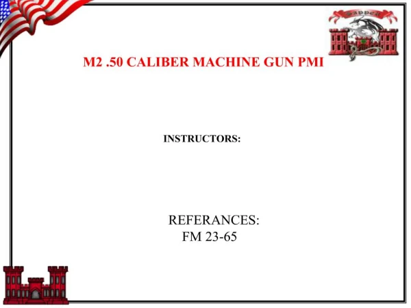
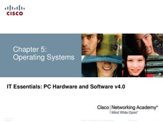
3 1 3 1 . . Views of the Computer • Application Programs • OS Utilities • Hardware Peripherals User’s View • HLL (e.g. C, C++, Pascal) • Machine independent • Assembly Language • Instructions • Memory • Registers Programmer’s View • Data path • Registers, ALU, etc. • Control Unit • Externals • Memory System • I/O System Architect’s View I R 2 . . 0 3 B u s D e c o d e r 0 5 4 3 2 1 0 Logic Designer’s View 1 0 = 3 2 0 Q D 0 C O N Q C N i n O 0 < 0
Fig 1.1 The User’s View of a Computer The user sees software (applications and OS), speed, storage capacity, and peripheral device functionality.
HLL Programmer’s View • High Level Language - C, C++, Pascal, etc. is used to program the machine for a specific application • Standard language makes the application “machine independent” • Compiler maps HLL to machine-specific instructions • Amount and type of “resources” may be evident • Amount of memory • Disk space • External devices • HLLs can be used to develop low-level code • Device drivers and OS’s written in C, and C++
Machine/Assembly Language Programmer’s View • Machine language: • Set of fundamental instructions the machine can execute • Expressed as a pattern of 1’s and 0’s • Assembly language: • Alphanumeric equivalent of machine language • Mnemonics more human-oriented than 1’s and 0’s • Assembler: • Computer program that transliterates (one-to-one mapping) assembly to machine language • Computer’s native language is machine/assembly language • “Programmer,” as used in this course, means machine/assembly language programmer
Machine and Assembly Language • The assembler converts assembly language to machine language. You must also know how to do this. Op code Data reg. #5 Data reg. #4 MC68000 Assembly Language Machine Language MOVE.W D4, D5 0011 101 000 000 100 ADDI.W #9, D2 0000 000 010 111 100 0000 0000 0000 1001 Tbl 1.2 Two Motorola MC68000 Instructions
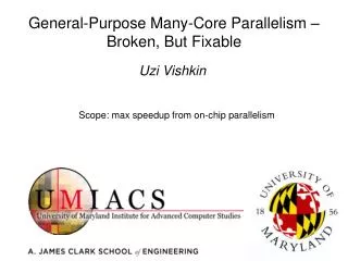
The Stored Program Concept • It is the basic operating principle for every computer. • It is so common that it is taken for granted. • Without it, every instruction would have to be initiated manually. The stored program concept says that the program is stored with data in the computer’s memory. The computer is able to manipulate it as data—for example, to load it from disk, move it in memory, and store it back on disk.
M C 6 8 0 0 0 C P U M a i n m e m o r y 3 1 0 0 V a r i o u s C P U r e g i s t e r s 4 0 0 0 0 0 1 1 1 0 1 0 0 0 0 0 0 1 0 0 1 5 0 P C 4 0 0 0 1 5 0 3 1 2 – 1 I R 0 0 1 1 1 0 1 0 0 0 0 0 0 1 0 0 1 5 0 C o n t r o l s i g n a l s T h e c o n t r o l u n i t Fig 1.2 The Fetch-Execute Process
Assembly Language Programmer’s Model:Instruction Set Architecture (ISA) • Instruction set: the collection of all machine operations. • Programmer sees set of instructions, along with the machine resources manipulated by them. • ISA includes • Instruction set, • Memory, and • Programmer-accessible registers of the system. • There may be temporary or scratch-pad memory used to implement some function is not part of ISA. • Not Programmer Accessible.
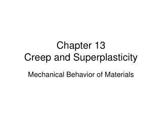
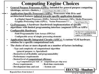
M 6 8 0 0 I 8 0 8 6 V A X 1 1 P P C 6 0 1 ( i n t r o d u c e d 1 9 7 5 ) ( i n t r o d u c e d 1 9 7 9 ) ( i n t r o d u c e d 1 9 8 1 ) ( i n t r o d u c e d 1 9 9 3 ) 7 0 1 5 8 7 0 3 1 0 0 6 3 0 A A X R 0 3 2 6 4 - b i t B X 1 5 B D a t a 1 2 g e n e r a l f l o a t i n g p o i n t r e g i s t e r s p u r p o s e C X R 1 1 I X 6 s p e c i a l r e g i s t e r s r e g i s t e r s p u r p o s e D X 3 1 A P S P r e g i s t e r s P C F P 0 3 1 S P S t a t u s A d d r e s s S P 0 3 2 3 2 - b i t B P a n d P C g e n e r a l c o u n t S I p u r p o s e r e g i s t e r s D I r e g i s t e r s P S W 3 1 C S M e m o r y 0 3 1 D S 0 0 3 2 s e g m e n t 2 b y t e s 1 6 2 b y t e s S S r e g i s t e r s o f m a i n M o r e t h a n 5 0 o f m a i n m e m o r y 3 2 - b i t s p e c i a l m e m o r y E S c a p a c i t y p u r p o s e c a p a c i t y 3 2 1 6 2 – 1 2 – 1 r e g i s t e r s I P M o r e t h a n 3 0 0 S t a t u s F e w e r i n s t r u c t i o n s t h a n 1 0 0 0 0 i n s t r u c t i o n s 5 2 2 b y t e s 2 0 2 b y t e s o f m a i n o f m a i n m e m o r y m e m o r y c a p a c i t y c a p a c i t y 5 2 2 0 2 – 1 2 – 1 M o r e t h a n 2 5 0 M o r e t h a n 1 2 0 i n s t r u c t i o n s i n s t r u c t i o n s Programmer Accessable RegistersFig 1.3 Programmer’s Models of 4 Commercial Machines
Machine, Processor, and Memory State • The Machine State: contents of all registers in system, accessible to programmer or not • The Processor State: registers internal to the CPU • The Memory State: contents of registers in the memory system • “State” is used in the formal finite state machine sense • Maintaining or restoring the machine and processor state is important to many operations, especially procedure calls and interrupts
Data Type: HLL Versus Machine Language • HLLs provide type checking • Verifies proper use of variables at compile time • Allows compiler to determine memory requirements • Helps detect bad programming practices • Most machines have no type checking • The machine sees only strings of bits • Instructions interpret the strings as a type: usually limited to signed or unsigned integers and FP numbers • A given 32-bit word might be an instruction, an integer, a FP number, or 4 ASCII characters
Tbl 1.3 Instruction Classes • This compiler: • Maps C integers to 32-bit VAX integers • Maps C assign, *, and + to VAX MOV, MPY, and ADD • Maps C goto to VAX BR instruction • The compiler writer must develop this mapping for each language-machine pair
Assembly Language Level Machine Language Level Physical Level Programming Levels • Application Commands • Scripts • Macros Application Level HLL Level • HLL Constructs Compiler • Assembly Language ISA Mnemonics • Assembler Directives Assembler • Location independent machine code Linker - Loader - OS • Executable memory image
Tools of the Assembly Language Programmer’s Trade • The assembler • The linker • The debugger or monitor • The development system
Who Uses Assembly Language • The machine designer • Must implement and trade off instruction functionality • The compiler writer • Must generate machine language from a HLL • The writer of time or space critical code • Performance goals may force program-specific optimizations of the assembly language • Special purpose or imbedded processor programmers • Special functions and heavy dependence on unique I/O devices can make HLLs useless
The Computer Architect’s View • Architect is concerned with design & performance • Designs the ISA for optimum programming utility and optimum performance of implementation • Designs the hardware for best implementation of the instructions • Uses performance measurement tools, such as benchmark programs, to see that goals are met • Balances performance of building blocks such as CPU, memory, I/O devices, and interconnections • Meets performance goals at lowest cost
Buses as Multiplexers • Interconnections are very important to computer • Most connections are shared • A bus is a time-shared connection or multiplexer • A bus provides a data path and control • Buses may be serial, parallel, or a combination • Serial buses transmit one bit at a time • Parallel buses transmit many bits simultaneously on many wires
Comp 1 Comp 2 Comp 3 Comp 1 Comp 2 Comp 3 tri-state bus ImplementationBuses vs. Multiplexors • Less area • Fewer components • Can be faster • More area • Some implementation technologies don’t allow tri-stat busses • Can be faster • Allows parallel transfers
Fig 1.4 Simple One- andTwo-Bus Architectures M e m o r y M e m o r y M e m o r y b u s C P U C P U I / O b u s I n p u t / I n p u t / o u t p u t o u t p u t s u b s y s t e m s u b s y s t e m n n - b i t s y s t e m b u s I n p u t / o u t p u t I n p u t / o u t p u t d e v i c e s d e v i c e s ( a ) O n e b u s ( b ) T w o b u s e s
Fig 1.5 The Apple Quadra 950Bus System (Simplified) L o c a l T a l k b u s P r i n t e r s , o t h e r L o c a l T a l k c o m p u t e r s i n t e r f a c e K e y b o a r d , A D B b u s A D B m o u s e , b i t p a d s t r a n s c e i v e r D i s k d r i v e s , S C S I b u s S y s t e m S C S I C D R O M d r i v e s b u s i n t e r f a c e V i d e o a n d s p e c i a l N u B u s N u B u s p u r p o s e c a r d s i n t e r f a c e C P U E t h e r n e t E t h e r n e t O t h e r c o m p u t e r s t r a n s c e i v e r M e m o r y
Fig 1.6 The Memory Hierarchy • Modern computers have a hierarchy of memories • Allows tradeoffs of speed/cost/volatility/size, etc. • CPU sees common view of levels of the hierarchy. C a c h e M a i n D i s k T a p e C P U m e m o r y m e m o r y m e m o r y m e m o r y
Tools of the Architect’s Trade • Software models, simulators and emulators • Performance benchmark programs • Specialized measurement programs • Data flow and bottleneck analysis • Subsystem balance analysis • Parts, manufacturing, and testing cost analysis
Logic Designer’s View • Designs the machine at the logic gate level • The design determines whether the architect meets cost and performance goals • Architect and logic designer may be a single person or team
Implementation Domains An implementation domain is the collection of devices, logic levels, etc. which the designer uses. • VLSI on silicon • TTL or ECL chips • Gallium arsenide chips • PLAs or sea-of-gates arrays • Fluidic logic or optical switches Possible implementation domains:
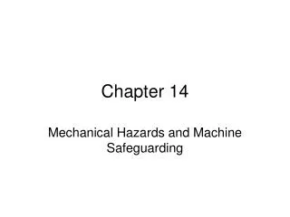
Fig 1.7 Three Implementation Domains for the 2-1 Multiplexer • 2-1 multiplexer in three different implementation domains • Generic logic gates (abstract domain) • National Semiconductor FAST Advanced Schottky TTL (VLSI on Si) • Fiber optic directional coupler switch (optical signals in LiNbO3) U 6 1 5 / G 1 / A / B S 2 1 A 4 1 Y 3 1 B 5 2 A 7 2 Y 6 2 B I 0 O S 1 1 3 A I 1 9 3 Y I 0 1 0 3 B O 1 4 4 A I 0 1 2 S 4 Y O 1 3 I 1 4 B I 1 7 4 F 2 5 7 N ( c ) O p t i c a l s w i t c h ( a ) A b s t r a c t v i e w o f ( b ) T T L i m p l e m e n t a t i o n i m p l e m e n t a t i o n B o o l e a n l o g i c d o m a i n
The Distinction Between Classical Logic Design andComputer Logic Design • The entire computer is too complex for traditional FSM design techniques • FSM techniques can be used “in the small” • There is a natural separation between data and control • Data path: storage cells, arithmetic, and their connections • Control path: logic that manages data path information flow • Well defined logic blocks are used repeatedly • Multiplexers, decoders, adders, etc.
31 0 Programmer: PC Logic Designer (Fig 1.8): Two Views of the CPU PC Register
Tools of the Logic Designer’s Trade • Computer-aided design tools • Logic design and simulation packages • Printed circuit layout tools • IC (integrated circuit) design and layout tools • Logic analyzers and oscilloscopes • Hardware development system
Historical Generations • 1st Generation: 1946–59, vacuum tubes, relays, mercury delay lines • 2nd generation: 1959–64, discrete transistors and magnetic cores • 3rd generation: 1964–75, small- and medium-scale integrated circuits • 4th generation: 1975–present, single-chip microcomputer • Integration scale: components per chip • Small: 10–100 • Medium: 100–1,000 • Large: 1000–10,000 • Very large: greater than 10,000
Chapter 1 Summary • Three different views of machine structure and function • Assembly Language Programmer’s View • Computer Architect’s View • Logic Designer’s View • Machine/assembly language view: registers, memory cells, instructions • PC, IR • Fetch-execute cycle • Programs can be manipulated as data • No, or almost no, data typing at machine level • Architect views the entire system • Concerned with price/performance, system balance • Logic designer sees system as collection of functional logic blocks • Must consider implementation domain • Tradeoffs: speed, power, gate fan-in, fan-out