Download
1 / 1
10 likes | 111 Views
WAKEFIELD SUPPRESSION IN THE MAIN LINACS OF CLIC Vasim Khan The Cockcroft Institute of Accelerator Science and Technology, Daresbury , Warrington, WA4 4AD School of Physics and Astronomy, The University of Manchester, Manchester M13 9PL, UK. Introduction

E N D
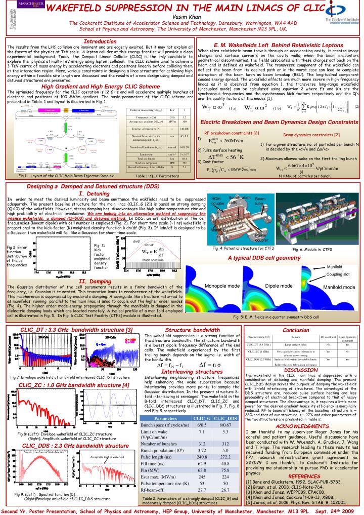
WAKEFIELD SUPPRESSION IN THE MAIN LINACS OF CLICVasim KhanThe Cockcroft Institute of Accelerator Science and Technology, Daresbury, Warrington, WA4 4AD School of Physics and Astronomy, The University of Manchester, Manchester M13 9PL, UK. Introduction The results from the LHC collision are imminent and are eagerly awaited. But it may not explain all the facets of the physics at TeV scale. A lepton collider at this energy frontier will provide a clean experimental background. Today, the Compact Linear Collider (CLIC) is the only candidate to explore the physics at multi-TeV energy using lepton collision. The CLIC scheme aims to achieve a 3 TeV centre of mass energy by accelerating electrons and positrons linearly before colliding them at the interaction region. Here, various constraints in designing a linac structure for achieving high energy within a feasible site length are discussed and the results of a new design using damped and detuned structures are presented. E. M. Wakefields Left Behind Relativistic Leptons When ultra relativistic beam travels through an accelerating cavity, it creates image charges and surface currents on the cavity walls, when the beam encounters geometrical discontinuities, the fields associated with these charges act back on the beam and is defined as wakefield. The transverse component of the wakefield can deflect the beam from its desired path or in the worst case can lead to complete disruption of the beam kwon as beam breakup (BBU). The longitudinal component causes energy spread. The wakefield effects are much more severe in high frequency linacs as it is observed from equation 1, the transverse long-range wakefield (uncoupled mode) can be calculated using equation 2 where f’s and K’s are the synchronous frequencies and the synchronous kick factors respectively and the Q’s are the quality factors of the modes [1]. High Gradient and High Energy CLIC Scheme The optimised frequency for the CLIC operation is 12 GHz and will accelerate multiple bunches of electrons and positrons at 100 MV/m gradient. The basic parameters of the CLIC scheme are presented in Table. 1 and layout is illustrated in Fig. 1. (1 a) (2) (1 b) Electric Breakdown and Beam Dynamics Design Constraints RF breakdown constraints [2] 1) 2) Pulse surface heating 3) Cost factor • Beam dynamics constraints [2] • For a given structure, no. of particles per bunch N is decided by the <a>/λ and Δa/<a> • 2) Maximum allowed wake on the first trailing bunch Fig 1: Layout of the CLIC Main Beam Injector Complex N = No. of particles per bunch Table 1: CLIC Parameters Acceleration cells HOM coupler Beam tube Designing a Damped and Detuned structure (DDS) I. Detuning In order to meet the desired luminosity and beam emittance the wakfields need to be suppressed adequately. The present baseline structure for the main linac (CLIC_G [2]) is based on strong damping (Q<10) of the wakefields. However, strong damping has disadvantages like high pulse temperature rise and high probability of electrical breakdown. We are looking into an alternative method of suppresing the intense wakefields, a damped (Q~500) and detuned method.In DDS, an erf distribution of the cell frequencies (lowest dipole) with cell number is employed (Fig. 2). For short time scale (~1 ns) wakefield is proportional to the kick-factor (K) weighted density function k dn/df (Fig. 3). If kdn/df is designed to be a Gaussian then wakefield will fall like a Gaussian for short time scale. Manifold Power coupler dn/df Kdn/df Fig 3: Kick factor weighted density function Fig 2: Error function distribution of the cell frequencies Fig 4: Potential structure for CTF3 Fig 6. Module in CTF3 A typical DDS cell geometry Mode spectrum Manifold Coupling slot II. Damping The Gaussian distribution of the cell parameters results in a finite bandwidth of the frequency, i.e. Gaussian is truncated. This truncation leads to recoherence of the wakefields. This recoherence is suppressed by moderate damping. A waveguide like structure referred to as manifolds, running parallel to the main linac is used to couple out the higher order modes (Fig. 4). The higher order mode energy propagating through the manifolds is dumped in the dielectric damping loads which are located remotely. A typical profile of a manifold employed cell is illustrated in Fig. 5. In Fig. 6 CLIC Test Facility (CTF3) module is illustrated. Monopole mode Dipole mode Manifold mode Fig 5: E. M. fields in a quarter symmetry DDS cell CLIC_DT : 3.3 GHz bandwidth structure [3] Structure bandwidth The wakefield suppression is a strong function of the structure bandwidth. The structure bandwidth is a lowest dipole frequency difference of the end cells. The wakefield experienced by the first trailing bunch depends on the sigma i.e. width of the bandwidth. Conclusion Discussion The wakefield in the CLIC main linac is suppressed with a combination of detuning and manifold damping. The present CLIC_DDS design serves the purpose of damping the wakefields with 8-fold interleaving of structures. The advantages of the DDS structure are, reduced pulse surface heating and less probability of electrical breakdown compared to that of heavy damped structures. The disadvantage is, it requires a little more power for the desired gradient hence its efficiency is marginally reduced. RF-to-beam efficiency of the baseline structure is ~ 28% and that of our structure is ~ 27% and other parameters of the two structures are presented in Table 2. Interleaving structures Interleaving neighbouring structure frequencies help enhancing the wake suppression because interleaving provides more points to sample the Gaussian distribution. In the present structure 8- fold interleaving is envisaged. The wakefield in the 8-fold interleaved CLIC_DT, CLIC_ZC and CLIC_DDS structures is illustrated in Fig. 7, Fig. 8 and Fig. 9 respectively. Fig 7: Envelope wakefield of an 8-fold interleaved CLIC_DT structure CLIC_ZC : 1.0 GHz bandwidth structure [4] ACKNOWLEDGMENTS I am thankful to my supervisor Roger Jones for his careful and patient guidance. Useful discussions have been conducted with W. Wuensch, A. Grudiev, J. Wang and T. Higo. The research leading to these results has received funding from European commission under the FP7 research infrastructure grant agreement no. 227579. I am thankful to Cockcroft Institute for providing me studentship to pursue PhD in accelerator physics. Fig 8: (Left): Envelope wakefield of CLIC_ZC structure (Right): Amplitude wakefield of CLIC_ZC structure CLIC_DDS : 2.3 GHz bandwidth structure Fourier transform of Wakefunction Acceptable limit on wakefield References [1] Bane and Gluckstern, 1992, SLAC-PUB-5783. [2] Braun, et al, 2008, CLIC-Note-764. [3] Khan and Jones, WEPP089, EPAC08. [4] Khan and Jones, Cockcroft-09-13, XB08. [5] Jones, et al, 2006, Phys. Rev. STAB, 9, 102001. Fig 9: (Left) : Spectral function [5] (Right)Envelope wakefield of CLIC_DDS structure Table 2: Parameters of a strongly damped (CLIC_G) and moderately damped (CLIC_DDS) structures Second Yr. Poster Presentation, School of Physics and Astronomy, HEP Group, University of Manchester, Manchester. M13 9PL Sept. 24th 2009