Download
1 / 53
530 likes | 793 Views
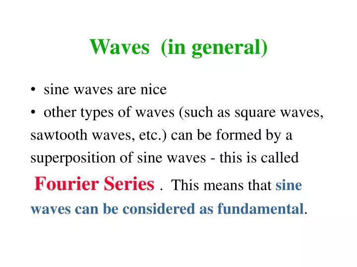
Waves (in general). sine waves are nice other types of waves (such as square waves, sawtooth waves, etc.) can be formed by a superposition of sine waves - this is called Fourier Series . This means that sine waves can be considered as fundamental . Waves (in general).

E N D
Waves (in general) • sine waves are nice • other types of waves (such as square waves, sawtooth waves, etc.) can be formed by a superposition of sine waves - this is called Fourier Series. This means that sine waves can be considered as fundamental.
Waves (in general) • E = Eosin()where is a phase angle which describes the location along the wave = 90 degrees is the crest =270 degrees is the trough
Waves (in general) E = Eosin() where is a phase angle in a moving wave, changes with both • time (goes2radians in time T) and • distance (goes 2radians in distance ) so = (2/)*x +/- (2/T)*t • where2/T = and • where 2/ = k and so phase speed: v =distance/time = /T = f =/k
Waves (in general) • For nice sine waves: E = Eo sin(kx +/- t) • For waves in general, can break into component sine waves; this is called spectral analysis
Light and Shadows • Consider what we would expect from particle theory: sharp shadows dark dark light
Light and Shadows • Consider what we would expect from wave theory:shadows NOT sharp crest crest crest dark dark dim light dim
Light and Shadows • What DOES happen? look at a very bright laser beam going through a vertical slit. (A laser has one frequency unlike white light.)
Double Slit Experiment • We will consider this situation but only after we consider another: the DOUBLE SLIT experiment:
Double Slit Experiment • Note that along the green lines are places where crests meets crests and troughs meet troughs. crest on crest followed by trough on trough
Double Slit Experiment • Note that along the dotted lines are places where crests meets troughs and troughs meet crests. crest on trough followed by trough on crest crest on crest followed by trough on trough
Double Slit Experiment • Further explanations are in the Introduction to the Computer Homework Assignment on Young’s Double Slit, Vol 5, #3. crest on trough followed by trough on crest crest on crest followed by trough on trough
Double Slit Experiment • Our question now is: How is the pattern of bright and dark areas related to the parameters of the situation: , d, x and L? bright x d bright L SCREEN
Young’s Double Slit Formula λ/d = sin() ≈ tan() = x/L The two (black) lines from the two slits to the first bright spot are almost parallel, so the two angles are almost 90 degrees, so the two ’s are almost equal. bright x d bright L λ
Double slit: an example n = d sin() = d x / L • d = 0.15 mm = 1.5 x 10⁻⁴ m • x = ??? measured in class • L = ??? measured in class • n = 1 (if x measured between adjacent bright spots) • = d x / L = (you do the calculation)
Interference: Diffraction Grating • The same Young’s formula works for multiple slits as it did for 2 slits. lens bright s1 s2 s3 s2 = s1 + s3 = s2 + = s1 + 2 s4 = s3 + = s1 + 3 s5 = s4 + = s1 + 4 d bright s4 s5 λ
Interference: Diffraction Grating • With multiple slits, get MORE LIGHT and get sharper bright spots. lens bright s1 s2 s3 s2 = s1 + s3 = s2 + = s1 + 2 s4 = s3 + = s1 + 3 s5 = s4 + = s1 + 4 d bright s4 s5
Interference: Diffraction Grating • With 5 slits, get cancellation when s = 0.8; with two slits, only get complete cancellation when s = 0.5 . lens bright dark s1 s2 s3 s2 = s1 + .8 s3 = s2 + .8 = s1 + 1.6 s4 = s3 + .8 = s1 + 2.4 s5 = s4 + .8 = s1 + 3.2 d bright s4 s5
Diffraction Grating: demonstrations • look at the white light source (incandescent light due to hot filament) • look at each of the gas excited sources (one is Helium, one is Mercury)
Interference: Thin Films • Before, we had several different parts of a wide beam interfering with one another. • Can we find other ways of having parts of a beam interfere with other parts?
Interference: Thin Films • We can also use reflection and refraction to get different parts of a beam to interfere with one another by using a thin film. reflected red interferes with refracted/reflected/refracted blue. air film water
Interference: Thin Films • Blue travels an extra distance of 2t in the film. reflected red interferes with refracted/reflected/refracted blue. air film t water
Interference: Thin Films • Also, blue undergoes two refractions and reflects off of a different surface. reflected red interferes with refracted/reflected/refracted blue. air film t water
Interference: Thin Films When a wave encounters a new medium: • the phase of the refracted wave is NOT affected. • the phase of the reflected wave MAY BE affected.
Interference: Thin Films • When a wave on a string encounters a fixed end, the reflected wavemust interfere with the incoming wave so as to produce cancellation. This means the reflected wave is 180 degrees (or /2) out of phase with the incoming wave.
Interference: Thin Films • When a wave on a string encounters a fixed end, the reflected wavemust interfere with the incoming wave so as to produce cancellation. This means the reflected wave is 180 degrees (or /2) out of phase with the incoming wave.
Interference: Thin Films • When a wave on a string encounters a free end, the reflected wavedoes NOT have to destructively interfere with the incoming wave. There is NO phase shift on this reflection.
Interference: Thin Films • When a wave on a string encounters a free end, the reflected wavedoes NOT have to destructively interfere with the incoming wave. There is NO phase shift on this reflection.
Interference: Thin Films • When light is incident on a SLOWERmedium (one of index of refraction higher than the one it is in), the reflected wave is 180 degrees out of phase with the incident wave. • When light is incident on a FASTER medium, the reflected wave does NOT undergo a 180 degree phase shift.
Interference: Thin Films • If na < nf < nw, BOTH red and blue reflected rays will be going from fast to slow, and no difference in phase will be due to reflection. reflected red interferes with refracted/reflected/refracted blue. air film t water
Interference: Thin Films • If na < nf > nw, there WILL be a 180 degree phase difference (/2)due to reflection. reflected red interferes with refracted/reflected/refracted blue. air film t water
Interference: Thin Films • There will ALWAYS be a phase difference due to the extra distance of 2t/. reflected red interferes with refracted/reflected/refracted blue. air film t water
Interference: Thin Films • When t=/2 the phase difference due to path is 360 degrees (equivalent to no difference) reflected red interferes with refracted/reflected/refracted blue. air film t water
Interference: Thin Films • When t=/4 the phase difference due to path is 180 degrees. reflected red interferes with refracted/reflected/refracted blue. air film t water
Interference: Thin Films • Recall that the light is in the FILM, so the wavelength is not that in AIR: f = a/nf. reflected red interferes with refracted/reflected/refracted blue. air film t water
Interference: Thin Films • reflection: no difference if nf < nw; 180 degree difference if nf > nw. • distance: no difference if t = a/2nf 180 degree difference if t = a/4nf • Total phase difference is sum of the above two effects.
Interference: Thin Films Total phase difference is sum of the two effects of distance and reflection • For minimum reflection, need total to be 180 degrees. • anti-reflective coating on lens • For maximum reflection, need total to be 0 degrees. • colors on oil slick
Thin Films: an example An oil slick preferentially reflects green light. The index of refraction of the oil is 1.65, that of water is 1.33, and or course that of air is 1.00 . What is the thickness of the oil slick?
Thin Films: an example • Since we have preferentially reflected green light, the TOTAL phase difference must be 0 degrees (or 360 degrees).
Thin Films: an example • Since we have preferentially reflected green light, the TOTAL phase difference must be 0 degrees (or 360 degrees). • Since we have nf > nw, we have 180 degrees due to reflection.
Thin Films: an example • Since we have preferentially reflected green light, the TOTAL phase difference must be 0 degrees (or 360 degrees). • Since we have nf > nw, we have 180 degrees due to reflection. • Therefore, we need 180 degrees due to extra distance, so need t = a/4nf where a = 500 nm, nf = 1.65, and so t = 500 nm / 4(1.65) = 76 nm.
Michelson Interferometer Split a beam with a Half Mirror, the use mirrors to recombine the two beams. Mirror Half Mirror Light source Mirror Screen
Michelson Interferometer If the red beamgoes the same length as the bluebeam, then the two beams will constructively interfere and a bright spot will appear on screen. Mirror Half Mirror Light source Mirror Screen
Michelson Interferometer If the blue beamgoes a little extra distance, s, the the screen will show a different interference pattern. Mirror Half Mirror Light source Mirror s Screen
Michelson Interferometer If s = /4, then the interference pattern changes from bright to dark. Mirror Half Mirror Light source Mirror s Screen
Michelson Interferometer If s = /2, then the interference pattern changes from bright to dark back to bright (a fringe shift). Mirror Half Mirror Light source Mirror s Screen
Michelson Interferometer By counting the number of fringe shifts, we can determine how far s is! Mirror Half Mirror Light source Mirror s Screen
Michelson Interferometer If we use the red laser (=632 nm), then each fringe shift corresponds to a distance the mirror moves of 316 nm (about 1/3 of a micron)! Mirror Half Mirror Light source Mirror s Screen
Michelson Interferometer We can also use the Michelson interferometer to determine the index of refraction of a gas (such as air). • Put a cylinder with transparent ends into one of the beams.
Michelson Interferometer • Evacuate the cylinder with a vacuum pump • Slowly allow the gas to seep back into the cylinder and count the fringes. Mirror Half Mirror Light source Mirror cylinder Screen
Michelson Interferometer • In vacuum, #vv = 2L . • In the air, #aa = 2L . • Since va < c, a < v and #a > #v . • Knowing v and L, can calculate #v .