Download
1 / 48
520 likes | 765 Views
A Review of Niobium (on Copper) Sputtering Technology. S. Calatroni. Introduction. Why films: advantages / disadvantages Residual resistance: topics for further R&D : Effect of roughness Effect of film structure Effect of hydrogen Effect of surface oxidation Conclusions and perspectives.

E N D
A Review of Niobium (on Copper) Sputtering Technology S. Calatroni
Introduction • Why films: advantages / disadvantages • Residual resistance: topics for further R&D : • Effect of roughness • Effect of film structure • Effect of hydrogen • Effect of surface oxidation • Conclusions and perspectives Sergio Calatroni - CERN - Sputtering Technology
Why films • Advantages (primary objectives) • Thermal stability • Cost • Innovative materials • Advantages (learned from experience) • Optimisation of RBCS at 4.2 K (sputtered niobium films) • Reduced sensitivity to earth magnetic field • Disadvantages (known from the beginning) • Fabrication and surface preparation (at least) as difficult as for bulk • Disadvantages (learned from experience) • Deposition of innovative materials is very difficult • Steep Rres increase with RF field (sputtered niobium films) Sergio Calatroni - CERN - Sputtering Technology
The surface resistance • The surface resistance can be written in the form: • Rs (HRF, Hext, T) = RBCS (HRF, T) + Rfl (HRF, Hext, T) + Rres (HRF) • The dependence of RBCS (0,T) on has been verified by changing the sputter gas • RBCS (HRF, T) has an intrinsic dependence of HRF • Rfl (HRF, Hext, T) has a dependence on similar to RBCS(0,T) Sergio Calatroni - CERN - Sputtering Technology
Theoretical and experimental BCS resistance at zero RF field 900 850 800 750 700 650 600 RBCS (4.2K) [n] 550 500 450 400 350 5 2 20 1 10 1+0/2 RBCS at 4.2 K Nb bulk: ~900 n Nb films: ~400 n RBCS at 1.7 K Nb bulk: ~2.5 n Nb films: ~1.5 n Nb bulk Sergio Calatroni - CERN - Sputtering Technology
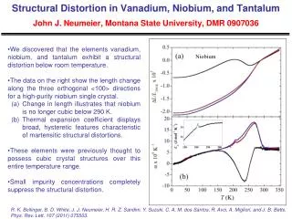
Fluxon-induced losses I (a) (b) 100 10 Rfl0[n/G] Rfl1[n/G/mT] 1 10 1 10 1 10 1+0/2 1+0/2 Fluxon-induced losses at 1.7 K are characterized as Rfl = (Rfl0 + Rfl1 HRF) Hext The minimum values are obtained using krypton as sputter gas: Rfl0 = 3n/G Rfl1 = 0.4 n/G/mT Triangles: bulk Nb Squares: coatings on oxide-free copper Circles: coatings on oxidized copper Sergio Calatroni - CERN - Sputtering Technology
Nb/Cu films – categories • There are two categories of films • Films which are intrinsically films • Thin, small grains, microstrained, under stress • Problems: defects & microstructure, (impurities), surface state • Examples: magnetron sputtered films on oxidised copper • The trend among workers is to aim for films which are bulk-like • Thick, large grains • Problems: hydrogen, surface quality • Examples: high-energy deposition techniques, annealed films, (Nb Cu-clad) Of course a film from one family may as well present all the problems typical of the other family… Sergio Calatroni - CERN - Sputtering Technology
Research lines around the world • Effect of substrate: roughness, thermal impedance • Non uniform coating, H enhancement (demagnetization), increased granularity. Thermal feedback • Optimisation of substrate preparation (electropolishing), study of angle-of-incidence effects, conformal coatings. Measurements of K • Film structure – defects • Hc1 reduction, hysteretic losses • Towards a bulk-like film: bias sputter deposition, high-energy deposition techniques, high-temperature annealing of films • Effect of hydrogen • Hydrides formation • Measurements of H2 contents, outgassings • Oxidation • Localized states, corrosion of grain boundaries • Al2O3 cap layers Sergio Calatroni - CERN - Sputtering Technology
Electropolishing – Polarization curve Standard Cu Electropolishing: 55% vol. H3PO4 45% vol. butanol Electrical resistance seen by the polishing current: Diffusion layer ~ 0.1 Bath volume ~ 0.1 (Nb EP bath: 10 times less) Production of Cu(OH)2 on the surface! Polishing Production of O2 bubbles! Sergio Calatroni - CERN - Sputtering Technology
Electropolishing – Cathode design Numerical modelling of the cathode by simulation of the entire EP process with the Elsy 2D/3D computer code (www.elsyca.be) Current density is uniform over all the cell surface Cathode active region Sergio Calatroni - CERN - Sputtering Technology
Measurement of pinholes Irregularities on the substrate surfaceshadowing effect film inhomogeneities He leak rate experiment ‹inc› fraction of leakyfilm surface - equator 9° 4.4 ppm - (~iris 50° 25 ppm) - equator 9° 0.1 ppm CP EP Substrate disk Machining and cleaning Film deposition Substrate removal p1 p2 film Sergio Calatroni - CERN - Sputtering Technology
Defects in Cu substrate Electropolished copper surface • average roughness: 0.02 µm • A few defects still appearing Cross section of a copper cavity • Defects are present inside ! • Not an artifact of the preparation Thanks to: G. Arnau-Izquierdo Sergio Calatroni - CERN - Sputtering Technology
Variation of properties with incidence angle AFM roughness XRD spectra From: V. Palmieri, D. Tonini – INFN-LNL Std.Dev. of grey levels of SEM images (CERN 1999) Sergio Calatroni - CERN - Sputtering Technology
Incidence angle and residual resistance in low- cavities Correlation between the incidence angle of the film and the residual resistance, measured on 352 MHz Nb/Cu cavities It seems there is a “threshold” effect Sergio Calatroni - CERN - Sputtering Technology
Angle of incidence – post magnetron – conformal coating B Magnetic field lines follow the cavity shape Cavity Niobium cathode V. Palmieri, R. Preciso, V.L. Ruzinov, S. Yu. Stark, “A DC Post-magnetron configuration for niobium sputtering into 1.5 GHz Copper monocells”, Presented at the 7th Workshop on RF Superconductivity Sergio Calatroni - CERN - Sputtering Technology
Angle of incidence in spherical cavity 80 Standard 1.5 GHz cavity 70 60 50 Average incidence angle of the Nb coating [degrees] 40 30 20 10 10 20 30 40 50 Length along the cavity axis [mm] 80 70 PACO cavity INFN Genova 60 50 Average incidence angle of the Nb coating [degrees] 40 The cathode is not point-like The incidence angle is always >0 30 20 10 20 40 60 80 Length along the cavity axis [mm] Sergio Calatroni - CERN - Sputtering Technology
Surface resistance of spherical cavity Standard 1.5 GHz Nb/Cu cavity Rs [Ohm] Rs [nOhm] 1.7 K Reducing the angle of incidence does not change Rs(E). However, the angle is always greater than zero, and whether this is creating any effect is only matter of speculation – for the time being Sergio Calatroni - CERN - Sputtering Technology
Thermal impedance film-substrate Conflat flange T2 H2 T1 Conflat ring Sample The overall thermal impedance has been measured for pure Nb and Cu, and for Nb/Cu and Nb/Nb films, on 2-mm thick disks. Cu (RRR=100) EP 4300 ± 200 Wm-2K-1 Cu EP + 1.5 µm Nb 4100 ± 200 Wm-2K-1 Nb (RRR=180) EP 1200 ± 200 Wm-2K-1 Nb EP + 1.5 µm Nb 1000 ± 200 Wm-2K-1 Nb (RRR=670)(extrap.) 2500 ± 200 Wm-2K-1 (Still lower than Nb/Cu, but Nb cavities performs better at high field !!) The thermal impedance of the film (if existing) has no effect on Rres at high RF field Thanks to: G. Vandoni, J-M Rieubland, L. Dufay Sergio Calatroni - CERN - Sputtering Technology
Nb/Nb 1p5.1 Nb bulk cavity 1p5.2 Nb/Nb (quench limited) Thanks to: V. Palmieri, D. Reschke, R. Losito Sergio Calatroni - CERN - Sputtering Technology
Al substrate (better thermal conductivity) Al 99.999% purity: 10X thermal conductivity of Cu at 4.2 K Spinning + chemical polishing + coating Thanks to: V. Palmieri, G. Lanza Sergio Calatroni - CERN - Sputtering Technology
Film structure – FIB cross sections Grain size with Focussed Ion Beam micrographs Standard films Oxide-free films 0.5 µm 0.5 µm Courtesy: P. Jacob - EMPA Sergio Calatroni - CERN - Sputtering Technology
TEM views I – plan view 500nm 500nm Grain size ~ 100 nm Fibre texture Diffraction pattern: powder diagram Grain size ~ 1-5 µm Heteroepitaxy Diffraction pattern: zone axis [110] Sergio Calatroni - CERN - Sputtering Technology
TEM views II – cross section 500nm 500nm (110) fibre texture substrate plane Heteroepitaxy Nb (110) //Cu(010) Nb (110) //Cu(111) Nb (100) //Cu(110) Sergio Calatroni - CERN - Sputtering Technology
TEM views III - defects ~100 nm Crystallographic defects 200K 100K Sergio Calatroni - CERN - Sputtering Technology
High-energy deposition techniques • Crystalline defects, grains connectivity and grain size may be improved with an higher substrate temperature which provides higher surface mobility (important parameter is Tsubstrate/Tmelting_of_film) • However the Cu substrate does not allow heating • The missing energy may be supplied by ion bombardment • In bias sputter deposition a third electron accelerates the noble gas ions, removing the most loosely bound atoms from the coating, while providing additional energy for higher surface mobility • Other techniques allow working without a noble gas, by ionising and accelerating directly the Nb that is going to make up the coating • These techniques allow also to obtain • “conformal” coatings that follow • the surface profile better filling voids. “Structure Zone Model” Sergio Calatroni - CERN - Sputtering Technology
Nb/Cu bias deposition – First SEM images at CERN No bias Bias -60 V 5 µm Bias -100 V Bias -80 V Sergio Calatroni - CERN - Sputtering Technology
Biased sputtering at LNL Sergio Calatroni - CERN - Sputtering Technology
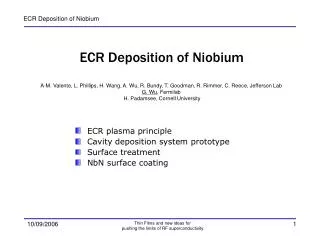
Evaporation + ECR (JLAB) • Niobium is evaporated by e-beam, then the Nb vapours are ionized by an ECR process. The Nb ions can be accelerated to the substrate by an appropriate bias. Energies in excess of 100 eV can be obtained. Generation of plasma inside the cavity 3 essential components: Neutral Nb vapor RF power (@ 2.45GHz) Static B ERF with ECR condition • Why ECR? • No working gas • High vacuum means reduced impurities • Controllable deposition energy, • 90-degree deposition flux • (Possible to help control the crystal structure) • Excellent bonding • No macro particles • Faster rate (Conditional) From: A.-M. Valente, G. Wu Sergio Calatroni - CERN - Sputtering Technology
Evaporation + ECR: results on samples • Obvious advantage: no noble gas for plasma creation • Sample tests: good RRR and Tc, 100-nm grain size, lower defect density and smooth surfaces 60eV TEM Images 3-D Profilometer Images 90eV 4000X4000 µm2 Sergio Calatroni - CERN - Sputtering Technology
Application to cavities (JLAB) Sergio Calatroni - CERN - Sputtering Technology
Plasma Arc (INFN) • In the plasma arc an electric discharge is established directly onto the Nb target, producing a plasma plume from which ions are extracted and guided onto the substrate by a bias and/or magnetic guidance • Magnetic filtering (and/or arc pulsing) is also necessary to remove droplets • A trigger for the arc is necessary: either a third electrode, or a laser • Arc spot moves on the Nb cathode • at about 10 m/s • Arc current is 100-200 A • Cathode voltage is ~ 35 V • Ion current is 100-500 mA on the sample-holder (2-10 mA/cm2) • Base vacuum ~ 10-10 mbar • Main gas during discharge is Hydrogen (~ 10-7 mbar) • Voltage bias on samples 20-100 V From: R. Russo, A. Cianchi, S. Tazzari Sergio Calatroni - CERN - Sputtering Technology
Plasma Arc – Need for filtering 10 µm Nb droplets 5 µm Nb droplets Magnetic filter Arc source Sergio Calatroni - CERN - Sputtering Technology
Planar arc – cavity deposition set-up 10 µm 5 µm New ideas are put forward for using a planar arc for cavity coating Sergio Calatroni - CERN - Sputtering Technology
Planar arc – RF measurements on samples! Cu samples with Nb ARC-coating. Used as a baseplate of 6 GHz cavity operating in the TE011 mode. At low field, the surface resistance is in the range 3÷6 µOhm, as compared to the BCS Rs of 0.22 µOhm at 2.2 K and small mean free path. The Q remained constant up to a field of 300 Oe. A baseline of 2.2 µOhm is measured with this cavity with a solid Nb plate Sergio Calatroni - CERN - Sputtering Technology
Liner arc for cavity deposition (Soltan Institute) Sergio Calatroni - CERN - Sputtering Technology
HPPMS: advantages From W. Sproul, AEI Sergio Calatroni - CERN - Sputtering Technology
Operating principle Principle: high power pulses of short duration • Peak value typically 100 times greater than conventional magnetron sputtering • Pulse width of 100 - 150 µsec, repetition rate ~50 Hz • Peak power densities of 1-3 kW/cm2 • Discharge voltages of 500-1000 V • Peak current densities ~ A/cm2 Consequences • High degree of target material ionization • High secondary electron current • Promotes ionization of sputtered species • Can approach 100%, vs. ~1% for conventional sputtering • An applied bias allows attracting ions to the substrate Sergio Calatroni - CERN - Sputtering Technology
Ion density From W. Sproul, AEI Sergio Calatroni - CERN - Sputtering Technology
HPPMS coatings in trenches (valid for any ion coating technique) J. Alami et Al, J.Vac.Sci.Technol. A23(2005)278 Sergio Calatroni - CERN - Sputtering Technology
First CERN results Pulse voltage (-500V/div) Current on sample (-100 V bias, 1A/div) Pulse current (100A/div) Sergio Calatroni - CERN - Sputtering Technology
First SEM pictures (all films ~100 nm thick) Substrate floating Substrate grounded Substrate biased -100V Note: poor substrate preparation Unfortunately no new experiments were possible since last year Sergio Calatroni - CERN - Sputtering Technology
Films as a bulk – Hydrogen becomes a problem! ~5 µm grain size, RRR 55 ~1 µm grain size, RRR 28 There are more differences between these Nb/Cu films than those listed, this is just a basis for reflection 0.1 µm grain size, RRR 11 H2 content is ~ 0.1 at. % for sputtered Nb/Cu films (in niobium bulk it is 0.02 at.%) and it is picked up from vacuum system during deposition. A possible solution: high-temperature annealing, but it does not work with copper cavities. Proposal (L. Hand, W. Frisken): molybdenum cavities. Sergio Calatroni - CERN - Sputtering Technology
Film as a bulk – H2 measurements There are new results on measurements of H2 content by measuring the lattice parameter and the total impurity content From: L. Hand, Cornell U. – W. Frisken, York U. Sergio Calatroni - CERN - Sputtering Technology
Grain boundaries and surface oxidation Famous drawings by Halbritter. Several effects might take place: ITE, flux penetration, Hc1 depression, lower Tc, etc. Sergio Calatroni - CERN - Sputtering Technology
Possible solution – Al2O3 cap layers • Technique routinely used for S-N-I-S Josephson junctions: a 5-nm thick Al layer is deposited onto the Nb base electrode, and let oxidize in air. Most of it is transformed to Al2O3 but some remains metallic. • It is important to prevent any surface contamination of Nb prior to Al coating, to reduce the coalescence of the Al atoms. • Other possible solution: NbN overlayer (J. Halbritter) XPS depth profile 5 nm Al (nominal) 10 nm Al (nominal) Sergio Calatroni - CERN - Sputtering Technology
State-of-the-art 20 years ago Sergio Calatroni - CERN - Sputtering Technology
State-of-the-art at 1500 MHz – 1.7 K – single cell Q 3x10⁹ @ 20 MV/m Q 1x10¹⁰ @ 15 MV/m 28 MV/m reached in a large LEP cryostat (He evaporation at large power) Sergio Calatroni - CERN - Sputtering Technology
Conclusion • In an ideal world niobium films would be the best solution for accelerating cavities at any beta. • However they are presently not competitive for reaching the highest fields because of the increase of Rres: WE MUST STRUGGLE AND UNDERSTAND WHY! • Films are still a valuable option for lower fields and operation at 4.2 K • The technique of choice is at present sputter deposition: a prerequisite for it is substrate design and its preparation • Four proposed research lines: • Substrate effects • New deposition techniques (“energetic”) • Hydrogen effects • Cap layers • Several of the above research lines are interdependent Sergio Calatroni - CERN - Sputtering Technology