Download
1 / 22
230 likes | 260 Views
An analytic model by Steve Shellhammer provides approximations of PHY and MAC layers to predict interference impact timely. The model factors in interferers' pulse and temporal characteristics, path loss, receiver filtering, and bit error rates.

E N D
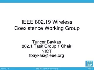
IEEE 802.19Wireless Coexistence TAG An Analytic Coexistence Assurance Model Steve Shellhammer shellhammer@ieee.org Steve Shellhammer, Intel Corporation
An Analytic CA Model • Make reasonable approximations of PHY and MAC layers. • Provide a method of predicting the impact of interference in a timely manner. • Not a detailed model intended to predict absolute performance of either system. • Is intended to predict relative impact of interference. • Only considering non-hoppers at this point • Intended as a first-order approximation. Steve Shellhammer, Intel Corporation
Model of Interferer • Interferer sends pulses • When transmitting a pulse the interferer is models in the frequency domain as band-limited white noise of power PT PT B fc fc + B/2 fc - B/2 Steve Shellhammer, Intel Corporation
Model of Interferer • Based on our knowledge of the interferer traffic the temporal model of the interferer is a stochastic process of pulses. Need to consider various models. • Distribution of pulse durations • Distribution of spacing between pulses Steve Shellhammer, Intel Corporation
Model of Interferer • Pulse TP duration is a random variable • Space TS between pulses is a random variable. TP TS TP TS TP Steve Shellhammer, Intel Corporation
Example of Pulse Model • The interferer is sending TCP IP packets. • There is an AP far away sending ACK packets. So we don’t consider this an interferer. • Throughput is about half the data rate. • TP = 1.0 ms • TS is a uniform RV • TS = U(30, 1300) us Steve Shellhammer, Intel Corporation
Path Loss Model • Some standard path loss model will be recommended, like the one used in 802.15.2. • Other path loss models could be used. • Give a topology of devices you can determine the interference power at the receiver based on path loss model. pl(d) = path loss in dB, with d in meters. Steve Shellhammer, Intel Corporation
Topology of Wireless Devices • One possible topology Transmitter Is not interfered with due to distance from interferers Does not interfere due to distance from NUT System A Network Under Test Receiver d System B Interferer Primary Interferer Steve Shellhammer, Intel Corporation
Receiver Model • Model receiver filter as an ideal brick wall filter, as far as interference goes. • The portion of the interfering signal that is within the passband of the receiver filter is pass though undisturbed • Any portion of the interfering signal outside the filter passband is eliminated entirely. Steve Shellhammer, Intel Corporation
Receiver Model NI Interferer PSD at Receiver • Noise after the receiver filter is the same height as before the filter, but possibly a smaller bandwidth 1 Receiver Filter NI Steve Shellhammer, Intel Corporation
Bit Error Rate • It is assumed that there is formula for BER for the receiver in AWGN. ber() = BER versus SNR for AWGN. • There are two periods of stationarity when we want to calculate the BER (which will help us get PER) • During a portion of the received packet when there is no interference during the packet • During a portion of the received packet when there is no interference during the packet Steve Shellhammer, Intel Corporation
Bit Error Rate • BER when there is no interference is based on thermal noise. • Since this is not very high we can • Assume it is very low • Or set up realistic topology and calculate BER • Since absolute performance is not a primary concern method one is recommended. Steve Shellhammer, Intel Corporation
Bit Error Rate • BER when interference is present is based on equivalent AWGN. • Pick AWGN level that would give equivalent power after the receiver filter. Steve Shellhammer, Intel Corporation
Bit Error Rate 1 Receiver Filter BF NI BAF BAF ) ( NI BF BAF Steve Shellhammer, Intel Corporation
Effective AWGN • Power after receiver is NI BAF • To get the same power after filter we have to have, Neff BF = NI BAF • The issue is that the interfere may not be as wide as filter. So we are dropping the PSD and widening the bandwidth • This is another approximation Steve Shellhammer, Intel Corporation
Bit Error Rate Summary • We now have a method to calculate the BER when there is no interference and when there is interference. • Calculate Eb from path-loss • With no interference use N0 • With interference use Neff • Can also add N0 to Neff Steve Shellhammer, Intel Corporation
Packet Error Rate • A packet in the network under test (NUT) is sent from transmitter to the receiver. There is a (possible) overlap between that packet and an interfering pulse. TD T Steve Shellhammer, Intel Corporation
Probability Analysis • Calculate probability density function for the random variable T. (Work still to be done). • T is a mixed random variable. There will be a finite probability that T is zero, and some density function over the interval (0,TD) Steve Shellhammer, Intel Corporation
Probability Density of T • An example of a PDF for T ½ fT(t) 1/(2T) 0 TD Steve Shellhammer, Intel Corporation
Packet Error Rate • Step 1 • Calculate PER for a fixed value of T • Step 2 • Average over all values of T using the previously calculated PDF for T • Step 3 • If necessary, average over packet duration, TD, assuming it is variable Steve Shellhammer, Intel Corporation
Other Metrics • Calculate other metrics based on PER and necessary approximations (e.g. independence) • Throughput • Latency • Packet Loss Rate (assuming a fixed time to complete transmission) • Other Steve Shellhammer, Intel Corporation
Conclusions • Outlined an approach to analytic solution. • Next steps • Work out technique for determining PDF of collision time. • Write up document giving details. • Apply to an example and use for comparison with other techniques. Steve Shellhammer, Intel Corporation